This post is about microphone back-end design: it shows how a microphone’s interoperability requirements—which specify which types of devices it must work with—drive key aspects of its design.
- The microphone back-end
- How interoperability requirements drive microphone back-end design
- Microphone interfacing scenarios
- Wrap-up
The microphone back-end
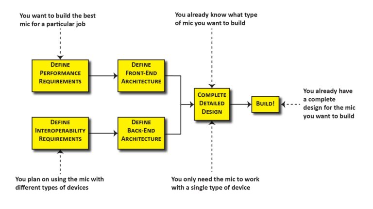
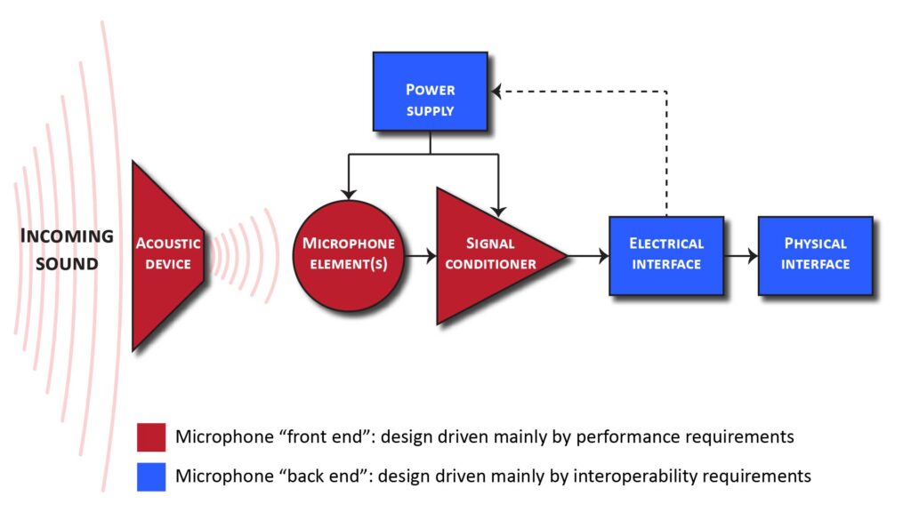
In Part 1 of this series (Basic DIY microphone design—Part 1: the microphone design process), I discussed the overall microphone design process and how a microphone can be decomposed into a front-end (that largely determines performance) and a back-end (that largely determines the types of devices the microphone can be used with). This post is about microphone back-end design, which addresses the items shown in blue in the following block diagram:
How interoperability requirements drive microphone back-end design
Even if our microphone meets all our performance requirements, it will be useless if it’s incompatible with the devices we plan to use it with.
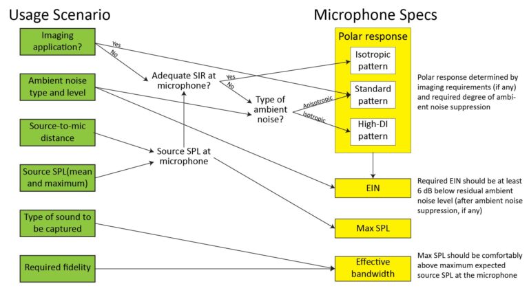
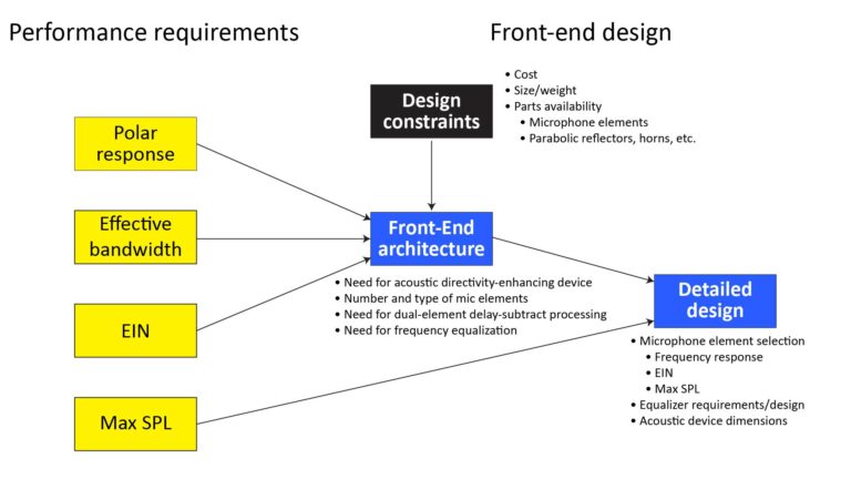
If we’re designing a microphone to work with only one specific device, then interoperability isn’t a big issue: we can just design the microphone’s power supply, electrical interface, and physical interface to match the device’s input characteristics. The following chart shows how the interoperability requirements drive the microphone back-end design:
But more typically, you’ll want your DIY microphone to be usable with a variety of devices, such as DSLRs, field recorders, audio interfaces, laptops, smartphones, etc. Unfortunately, no single microphone design will directly work with all devices that have a microphone input. So the approach that makes the most sense is to design the microphone for compatibility with the type of devices you expect to use the most, and rely on properly-designed adapters for when you have to use the microphone with other devices.
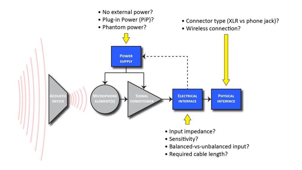
There are five characteristics of a device’s microphone input that have implications for microphone design:
- Balanced-versus-unbalanced input configuration
- Device input sensitivity (or, equivalently, full-scale signal input voltage)
- Input impedance
- Connector type
- Provided microphone power, if any
Fortunately, a microphone with a balanced output will work with both unbalanced and balanced inputs, and a microphone with a low output impedance will work with both low and high input impedances. So, assuming we design our microphone to have a low-impedance balanced output, we only have to worry about three design variables from the standpoint of interoperability:
- Full-scale signal microphone output voltage (or, equivalently, the downstream device’s full-scale input voltage)
- Connector type
- Provided microphone power (if any)
Full-scale signal input voltage
Audio inputs can be grouped into three categories based on the full-scale signal voltage they expect:
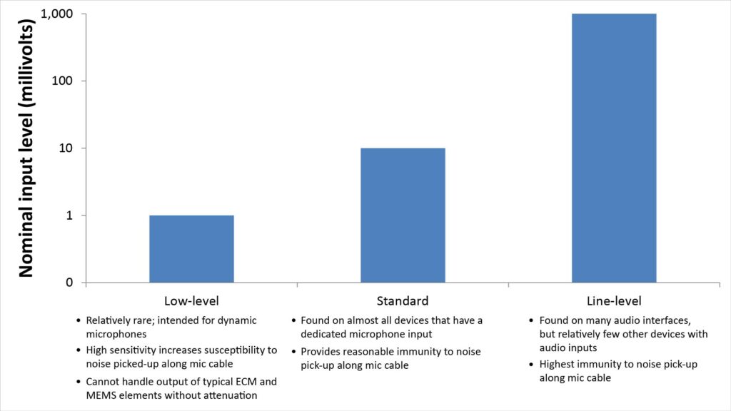
- Low-level microphone inputs expect a full-scale input voltage of the Order Of Magnitude (OOM) of 1 mV. This is the typical OOM output level of dynamic microphones.
- Standard-level microphone inputs expect a full-scale input voltage of OOM 10 mV. This is the typical OOM output level of the powered microphones which represent the bulk of the microphones in use today. These include microphones based on small, low-voltage Electret Condenser Microphone (ECM) elements, larger diameter, Externally-Polarized Condenser (EPC) elements, and Micro-Electro-Mechanical Systems (MEMS) microphone elements.
- Line-level inputs expect a full-scale input voltage of OOM 1 V. Actually, consumer-grade line-level inputs, called Aux inputs, expect a bit less (around 0.3 V), but still within the same OOM.
The vast majority of devices we’re going to want to drive with our DIY microphone will have a standard-level mic input or a line-level input, so there’s isn’t much need to design a DIY mic to intentionally produce a low-level output signal. That leaves standard-level and line-level output voltages.
Not surprisingly, most microphones are designed to produce an output voltage compatible with standard-level microphone inputs. But a microphone capable of producing a line-level output offers a significant advantage: since the voltage is 20 dB greater than a standard-level output (1V versus 10 mV), any electrical noise picked up on the wiring between the microphone and the downstream device will be suppressed by 20 dB due to the reduced voltage sensitivity of the line-level input. However, even with a 10 mV output, the noise at the downstream device is usually dominated by ambient acoustic noise rather than electrical noise picked-up on the cable. So, the added 20 dB of suppression from a 1V output level typically has a negligible impact on performance.
Also, there are three disadvantages associated with designing for a line-level output:
- not every audio input device has a line-level input;
- we’d need a more capable preamplifier to generate the line-level output; and
- if the mic is battery-powered, the battery life is going to be shorter (or we’re going to need a larger battery) than if the output were just 10 mV.
Based on the above considerations, designing for a 10 mV nominal output voltage generally makes the most sense. One exception would be an ultra-low-noise microphone intended for use in a quiet studio, when the downstream device is known to have a line-level input; in that case, designing for a 1V line-level output can maximize the overall signal-to-noise ratio (with careful design of the buffer/preamp built-in to the microphone). But even then, the added benefit of a line-level output will be modest, and generally not worth the complexity.
Fortunately, since most DIY microphones are based on ECM or EPC elements (which natively produce a ~10 mV output voltage), this aspect of microphone back-end design is usually a non-issue.
Connector type
If we exclude low-level and line-level inputs, most of the devices we’d want to drive with a DIY microphone will have one of three types of mic input jack/pinout:
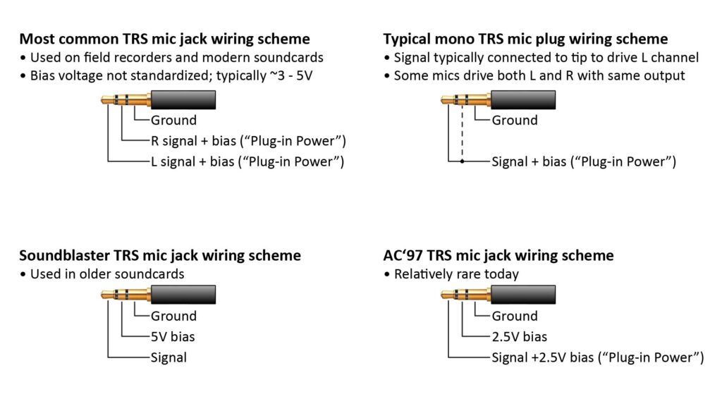
- 3.5 mm (1/8-inch) Tip-Ring-Sleeve (TRS) phone jack. This is the most common microphone input connector, and there are a variety of microphone wiring schemes which use it. The most popular of these is shown in the upper left of Figure 4; this scheme accommodates stereo (Left and Right) microphone signals by supplying Plug-in Power (PiP) on two separate terminals. However, most microphones are mono (they have only a single channel output), so they are wired as shown in the upper right of the figure: the output is either connected to just the tip terminal (which is the Left channel input on most devices), or the output is connected to both the tip and ring terminals (so that the output drives both the Left and Right channels).
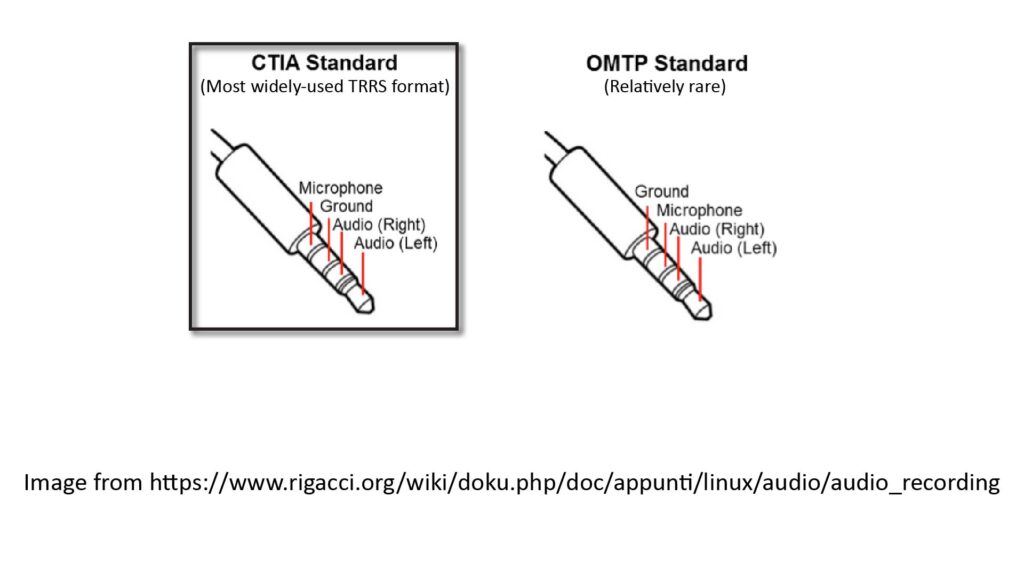
- 3.5 mm (1/8-inch) Tip-Ring-Ring-Sleeve (TRRS) phone jack per the Cellular Telephone Industries Association (CTIA) standard, as shown in Figure 5. This has the microphone (with optional DC bias) on the Sleeve, and the ground is on the Ring closest to the Sleeve.
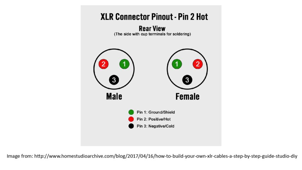
- XLR3 (3-pin) jack, as shown in Figure 6. This has ground on pin 1, and balanced signals on pins 1 and 2.
Balanced versus unbalanced signals and connector configuration
High-performance microphone inputs use a differential input stage that expects a pair of balanced microphone signals. Balanced signals have the same amplitude but opposite polarity, and the differential stage produces an output that’s the difference between the two signals. The benefit is that any common-mode noise picked-up in the input cabling—which is noise that affects both signals equally—is subtracted-out in the differential input stage.
There are two requirements to obtain this benefit:
- Both signal paths from the microphone to the differential input stage must have the same impedance. This has nothing to do with the type of connector, and is affected only by the design of the input stage and (to a lesser extent) the cable.
- Both signal paths must be equally well (or equally poorly) shielded from electrical noise. This does depend on the connector configuration to some extent (as well as the cable). However, with the right cable configuration, the type of connector has only a small effect on noise pick-up and rejection.
All audio devices that have XLR3 inputs also have differential input stages that expect balanced signals, and all XLR3 connectors and cables are configured to ensure the best possible balance between the two signals to maximize common-mode noise suppression.
Conversely, many audio devices that have phone-jack microphone inputs do not have differential input stages or balanced input impedances. However, some do. And while a phone-jack interface isn’t ideal for carrying balanced signals, there’s nothing to preclude it from carrying balanced signals—and with the right type of input stage and cable, it will provide almost as much common-mode rejection as an XLR set-up. So any DIY microphone that uses a phone-jack interface can (and probably should) be designed for balanced signals.
Which connector to design for?
Of the microphone input-connector types shown above, the most common across all devices is the 3.5 mm TRS type—and it’s also the smallest and least-expensive type of wide-used microphone connector. However, the most common microphone input-connector type across high-performance audio devices is the XLR3.
Fortunately, it’s possible to use adapters to connect a 3.5 mm TRS plug with an XLR jack, and vice-versa—but it can be tricky. That’s because the connectors sometimes supply power to the microphone (as well as accepting the microphone’s output signal), and the two types use differing power standards.
Microphone power
As has been the case for many decades, most of the microphones in use today require external power: microphones using ECMs and MEMS elements require a few volts, while those using EPC capsules require a few tens of volts (dynamic mics per se don’t need any power, but they need a preamp for use with standard-level inputs…and if the preamp is built-into the microphone to minimize noise pick-up, then the mic will need power for the preamp).
If we include include a battery, USB, or mains-powered supply in our DIY microphone, then we can eliminate microphone power as an interoperability issue. On the other hand, having to worry about batteries or plugging-in a USB or line cord can be inconvenient.
Fortunately, most microphone inputs today provide some form of microphone power: either Plug-in Power (PiP) or Phantom Power (PP). The power is supplied by the same cable and connector that accepts the microphone output signal, which is very convenient.
From a design standpoint, another convenient fact is that any device that supplies PiP almost always has a 3.5 mm connector, and any device that supplies PP almost always has an XLR connector. So, if we design for one type of external power, we only have to design for one type of connector.
However, relying on either PiP or PP does present potential performance issues (as I’ll discuss in the next section).
So, selecting the power source for a DIY microphone comes down to a trade between performance (which favors a dedicated microphone power supply) and convenience (which favors either PiP or PP).
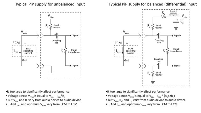
Plug-In Power (PiP)
Almost all consumer-grade microphones use ECM capsules, so almost all consumer-grade audio inputs provide a few volts of what is known as Plug-in Power (PiP).
PiP is very convenient. However, that convenience comes at the expense of performance, for two reasons:
- Every mic capsule that can use PiP power expects a certain PiP supply voltage and load resistance, whereas the actual PiP voltage and load resistance vary from device to device. Therefore, it’s unlikely that any given mic capsule used with a given PiP supply will see the optimum voltage and load resistance. And if a mic capsule doesn’t see the optimum supply voltage and load resistance, it won’t provide its full specified performance (sensitivity, dynamic range, SNR, maximum SPL capacity, and THD could all be affected).
- PiP voltage can sometimes contain significant noise from the digital circuitry in the supplying device, which can raise the noise floor if the device doesn’t also have a differential input stage to suppress common-mode noise.
I’ll discuss these issues in more detail in my post on why you should avoid Plug-in-Power for a high-performance DIY microphone; as the title implies, it’s best not to rely on PiP power to power a DIY microphone if you care about performance. Fortunately, just because a device supplies PiP doesn’t mean a mic has to actually use it.
Phantom Power (PP)
Externally-polarized condenser elements are used only in more expensive microphones, so the tens of volts they require is provided only in prosumer or professional-grade audio equipment, via what is known as Phantom Power (PP).
Unlike PiP, the supply voltage and load resistance of PP is pretty consistent from device to device: although there are three voltage standards (12, 24, and 48V), each with different load resistances, almost all devices that supply PP are compliant with the 48V standard (which specifies 6.8K load resistors). So a microphone that expects PP can be safely designed for 48V/6.8K with the expectation of wide interoperability.
Also, while PP can contain noise generated by the device that supplies, PP is usually much quieter than PiP, and all devices that supply PP have differential input stages that suppress common-mode noise.
However, PP can also present a couple of challenges for the DIY mic builder:
- Most DIY mics require much less than 48V, so the mic will need to include some form of voltage regulator.
- Most modern devices that supply PP are capable of only sourcing up to 10 mA of current…and some aren’t even capable of sourcing that much.
The first issue is easily overcome, but the second could be a significant problem for DIY mic designs that need more than 10 mA. Fortunately, it’s not hard to stay within 10 mA unless you need a very specialized design.
Microphone interfacing scenarios
For the reasons described above, the majority of DIY microphones will be based on ECM or EPC microphone elements, and will be used with just two types of microphone inputs:
- Unbalanced inputs with optional PiP, typically with 3.5 mm TRS jacks. These are found on small devices (such as lower-cost field recorders and cameras); computers, laptops, and consumer-quality soundcards; and (with TRRS jacks) some smartphones and tablets.
- Balanced inputs with optional PP, typically with XLR jacks. These are found on larger and higher-quality prosumer devices (such as high-performance recorders, mixers, or audio interfaces).
If you’re building a microphone, it makes sense to design it for whichever of these two input types you expect to use most often, and to rely on DIY or commercial adapters when you need to use it with the other type of input.
When the microphone is designed for use primarily with unbalanced PiP-enabled inputs
As previously described, unbalanced inputs don’t provide the common-mode noise rejection achievable with balanced inputs, and devices with unbalanced inputs often have noisier input stages than device with balanced inputs.
However, these are non-issues in many applications because the effects ambient acoustic noise will often be much greater than the common-mode or input-stage noise contributions.
Plus, many devices with unbalanced inputs are far smaller (and therefore more portable) than those with balanced inputs; these include miniature field recorders, DSLRs, camcorders, and smartphones.
Yet another reason to design for unbalanced inputs is that they are found on desktop computers, laptops, and many USB soundcards; these are very useful for capturing a microphone signal because they can also run communications, recording, and signal-processing applications.
Figure 7 shows common interfacing scenarios for a microphone that is designed primarily for use with an unbalanced input which optionally provides PiP:
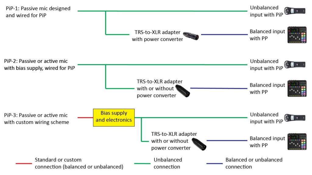
PiP-1: Passive microphone designed and wired for Plug-in Power
The PiP-1 scenario of Figure 7 is probably the most common, and first one many DIY microphone builders will encounter. It involves a passive microphone, which for the purposes of this post means one that doesn’t include a power source or any active electronic circuitry. In the vast majority of cases, the microphone element will be an Electret Condenser Microphone (ECM) element, which needs a bias voltage which it obtains from the PiP supply of the downstream audio device.
Such a microphone needs only an ECM element, a housing of some type (which, in the case of a lavalier mic, could just be a short length of heat-shrink tubing), a cable, and TRS or TRRS connector.
Another advantage is that the microphone can be used with the other type of audio device (one which has balanced inputs and provides PP) via a commercial or DIY adapter. This adapter must convert the TRS (or TRRS) microphone plug into an XLR plug, and must also convert the higher-voltage PP provided by the audio input into the lower-voltage PiP expected by the ECM element. Several manufacturers make such adapters, but the only ones I recommend are the Rode VXLR Plus and Rode VXLR Pro. The former provides an unbalanced output and costs about xxx; the latter provides a balanced output and costs about xxx.
The PiP-1 scenario is simple, versatile, and works well. However, as I explain in detail in xxxx, relying on PiP can result in some pretty significant performance issues. This applies both to PiP-enabled devices, as well as to even high quality adapters (like those by Rode) that convert PP into PiP.
PiP-2: Passive or active microphone with integral bias supply, wired for Plug-in Power
The PiP-2 scenario of Figure 7 is the same as the PiP-1 scenario, except that the microphone includes its own bias supply (which is usually a battery), a load resistor, and a coupling capacitor—and optionally additional electronics like a preamplifier or filter.
If you optimize the load resistor and battery voltage for the ECM element you’re using, you can usually obtain far better performance than if you just rely on PiP (either directly or via an adapter).
Plus, if you want to use such a microphone with a device with a balanced input and PP, the required adapter is less expensive because it doesn’t need to convert the PP to PiP. Such an adapter is the Rode VXLR, which costs only about $10.
However, there are a couple of potential downsides to the PiP-2 scenario:
- The battery (and potentially the coupling capacitor) are usually too large for inclusion in a lavalier or headset microphone. For such applications, it’s better to locate them in a separate module somewhere between the microphone and downstream audio device (see the PiP-3 scenario below).
- If you’re using the microphone with a device that provides PP via an adapter without a power converter (like the Rode VXLR), then you must either turn the PP off at the audio device to avoid damaging the coupling capacitor, or you must use one with a high enough voltage rating handle the PP (and such a capacitor will be significantly larger than one with a voltage rating for PiP). Alternatively, you can use an adapter that does include a power converter (like the VXLR Plus or VXLR Pro), which ensures that only a relatively low voltage will reach the coupling capacitor. One reason you might want to do this (even if you can turn off the PP) is to use a VXLR Pro to obtain a fully balanced connection between the adapter and the audio input.
PiP-3: Passive or active microphone with custom wiring scheme
The PiP-3 scenario of Figure 7 is the same as the PiP-2 scenario, except that the larger components (such as the battery and coupling capacitor) are located in a separate module between the microphone and the downstream audio device (we’ll call this the interface module). As mentioned above, this has the advantage of reducing the size of the microphone assembly, which is desirable for lavalier, headset, and parabolic or shotgun microphones.
With the PiP-3 scenario, the wiring scheme between the microphone and the interface module could be one of the standard wiring schemes (such as for PiP or PP), but it could also be something completely different. There are advantages to using a different wiring scheme, as discussed later in this post.
When the microphone is designed for use primarily with balanced PP-enabled inputs
If you’re building a microphone for use in a professional or home recording studio, such as for recording music or podcasts, you’ll probably want to design it to work best with balanced audio inputs that are capable of providing PP, such as those on a high-performance audio interface board or mix console. Figure 8 shows common interfacing scenarios for such a microphone:
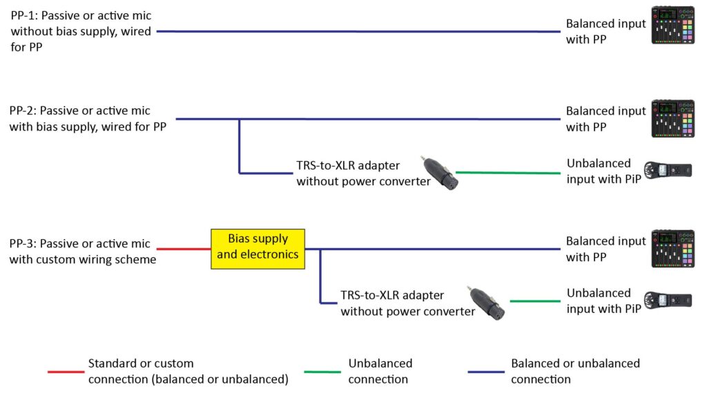
PP-1: Passive or active mic without bias supply, designed and wired for Phantom Power
The PP-1 scenario of Figure 7 is by far the most common interface scenario for a microphone designed primarily to work with PP. But unlike the PiP-1 scenario of Figure 8, if such a microphone uses an Electret Condenser Microphone (ECM) element, it must also include some additional components beyond the element itself:
- The simplest configuration is an ECM, load resistor, and coupling capacitor.
- More elaborate configurations include an ECM, load resistor, Zener-diode-based voltage converter, and optional active electronics.
Many Externally Polarized Condenser (EPC) microphone capsules can be powered directly from Phantom Power, so they require only a housing, cable, and connector for use in the PP-1 scenario.
A microphone designed for the PP-1 scenario can provide either an unbalanced output or a balanced output, depending on the implementation.
One disadvantage of a microphone designed for the PP-1 scenario is that it must be used with Phantom Power; it cannot be used with a device that supplies only PiP.
PP-2: Passive or active mic with bias supply, designed and wired for Phantom Power
The PP-2 scenario of Figure 8 is the same as the PP-1 scenario, except that the microphone includes its own bias supply (which is usually a battery), a load resistor, and a coupling capacitor—and optionally additional electronics like a preamplifier or filter. This configuration makes sense for microphones that require a low-voltage power source, such as ECM or MEMs elements, but not for higher-voltage EPC elements (which can be powered directly from 48V Phantom Power).
Note that this configuration is exactly the same as that of PiP-2 scenario of Figure 7, except that the microphone is wired with an XLR plug instead of a TRS plug. But, like the microphone of PiP-2—and unlike the microphone of PP-1—the PP-2 microphone can also be used with unbalanced inputs that provide PiP via an inexpensive XLR-female-to-TRS-male adapter that doesn’t include a power converter. Rode doesn’t make such an adapter, but you can find them on Amazon for around $10.
As with the PiP-2 scenario of Figure 7, the battery and coupling capacitor necessary for the PP-2 scenario are too large for inclusion in a lavalier or headset microphone. For such applications, it’s better to locate these components in a separate module somewhere between the microphone and downstream audio device (see the PP-3 scenario below).
PP-3: Passive or active microphone with custom wiring scheme
The PP-3 scenario of Figure 8 is the same as the PP-2 scenario, except that the larger components (such as the battery and coupling capacitor) are located in a separate module between the microphone and the downstream audio device (we’ll call this the interface module). In fact, this is identical to the PiP-3 scenario of Figure 7, except that the output of the interface module is wired for XLR rather than PiP.
As mentioned above, this has the advantage of reducing the size of the microphone assembly, which is desirable for lavalier, headset, and parabolic or shotgun microphones.
With the PiP-3 scenario, the wiring scheme between the microphone and the interface module could be one of the standard wiring schemes (such as for PiP or PP), but it could also be something completely different.
Non-standard mic wiring schemes for the PiP-3 and PP-3 scenarios
The PiP-3 and PP-3 shown above scenarios are appropriate for when the microphone assembly must be as small as possible; the best examples are probably lavalier and headset microphones (but they’re also useful for parabolic and shotgun mics, too). As shown in Figures 7 and 8, the wiring between the microphone assembly and the interface module in these scenarios could follow the standard PiP or PP wiring schemes, but it could be something completely different. Two custom wiring schemes, in particular, are potentially advantageous for these configurations.
Non-standard 3-conductor wiring scheme for passive ECM-based microphones
Figure 9 shows a non-standard 3-conductor wiring scheme between a passive ECM microphone module and an interface module, as in the PiP-3 scenario of Figure 7 or the PP-3 scenario of Figure 8. It uses a shielded two-conductor cable (the type usually intended for balanced microphone connections), such as the very thin and lightweight Mogami W2901 bulk cable, with the shield connected to ground on the interface module side, but not connected to either of the ECM terminals:
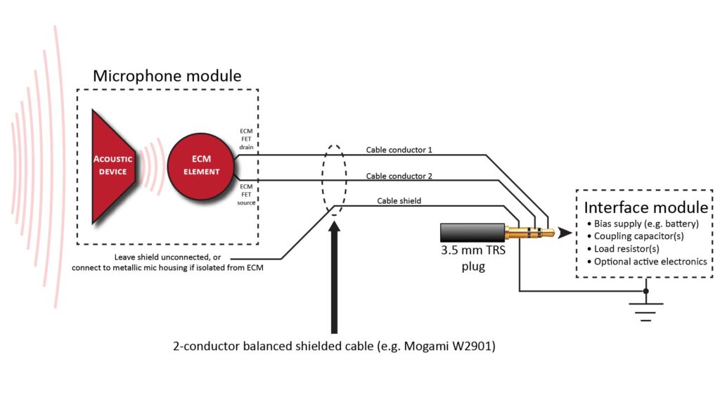
Actually, this wiring scheme is really only “non-standard” because of the TRS pin assignments, which are inconsistent with any of the standards shown previously in Figure 4.
The advantage of this scheme is that it provides better noise immunity on the cable between the microphone module and the interface module (although not nearly as much noise immunity as with the 4-conductor scheme described below). This scheme is very useful for miniature microphones (such as lavalier types) when you don’t want to rely on PiP. Of course, if you do want to rely on PiP, then one of the standard wiring schemes of Figure 4 would be more appropriate.
Non-standard 4-conductor wiring scheme for active or passive microphones
Figure 10 shows a non-standard 4-conductor wiring scheme for active or passive microphones:
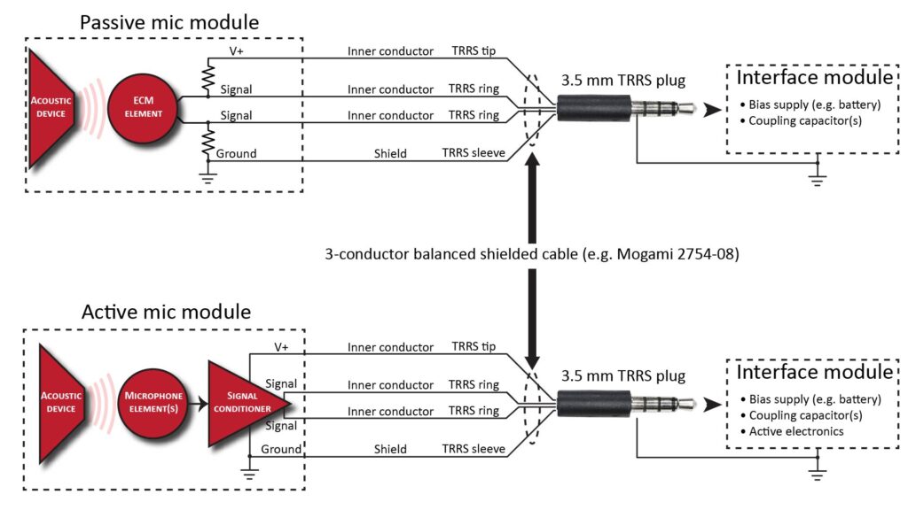
The use of 4 conductors allows separation of the signal and power connections, which maximizes flexibility and performance:
- Keeping the power separate from the signal (unlike Plug-in Power or Phantom Power) eliminates the need for relatively large DC-blocking capacitors in the microphone module and facilitates powering MEMS microphone elements and active circuitry.
- The two signal conductors (in addition to ground) allow a true differential connection which greatly suppresses any common-mode noise picked-up on the microphone cable.
The passive-microphone configuration at the top of the figure is very interesting, because it provides a true differential connection between the microphone and interface module with nothing more than a pair of load resistors inside the mic module. This is ideal for a high-performance lavalier or headset microphone set-up, in which the interface module (which holds the bias battery and coupling capacitors) can be on a belt clip or sitting on a desk.
Wrap-up
As we’ve seen, a microphone’s back-end architecture flows directly from its interoperability requirements, and defining it is a key part of the overall microphone design process (as described in Part 1 of this series). No single back-end design is optimum for every application, but thoughtful design and appropriate use of adapters can maximize convenience, performance, and interoperability.