Many audio inputs supply microphone Plug-In Power (PiP), which is an extremely convenient way to supply power to microphones that use Electret Condenser Microphone (ECM) elements. However, performance will suffer if the PiP supply isn’t matched to the specific ECM being used, and PiP isn’t optimal for microphones based on other types of low-voltage microphone elements (such as Micro-Electro-Mechanical Systems, or MEMS, elements) or those that include other active circuitry. This post explains how PiP supplies can degrade performance and introduces practical alternatives to powering a microphone with PiP.
- What is microphone Plug-in Power (PiP)?
- What the ECM expects: required bias voltage and load resistance
- What happens with different PiP voltages and load resistances
- Using microphone Plug-in Power for devices other than ECMs
- Is Plug-in Power limiting the performance of your microphone?
- Mitigating the limitations of microphone Plug-in Power
- The bottom-line: microphone Plug-in Power isn't ideal for high-performance microphones
- References
What is microphone Plug-in Power (PiP)?
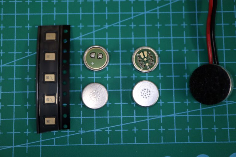
Because of their cost-effectiveness, the bulk of microphones in use today use Electret Condenser Microphone (ECM) microphone elements, and this has been true for decades. While an electret (which is effectively a “permanent condenser”) microphone element doesn’t require an external bias voltage, its output impedance is so high that it requires an impedance buffer to connect to any external device. In virtually all ECMs, this buffer is a Junction Field-Effect Transistor (JFET) and does require external power.
This power could be supplied by a battery mounted in the microphone, but can be impractical for microphones that need to be physically small (such as lavaliers). And in any case, the need to occasionally replace or recharge the battery is an inconvenience.
Fortunately, since whatever device the microphone is plugged into will also need (and therefore include) its own power supply, we can just rely on that device to also provide power for the microphone.
This power could be supplied by a dedicated conductor in the microphone cable. However, this increases the cost and size of the cable and connectors.
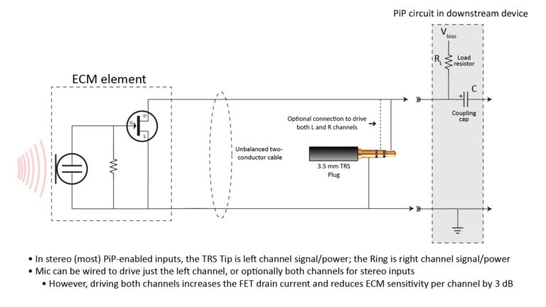
Fortunately, it’s possible to share power (which is DC) and signal (which is AC) on the same conductors by using a capacitor to separate them…and that’s what PiP does: microphone plug-in Power (PiP) is a way of supplying power to an Electret Condenser Microphone (ECM) element via the same two conductors that carry the microphone output signal.
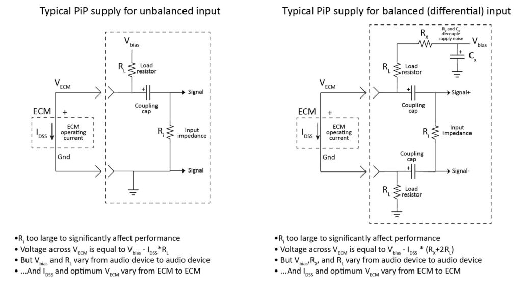
There are two basic variations of PiP circuits currently in use, but they both work the same way: a voltage source supplies the power through one or more resistors, while one or more capacitors block the DC bias and pass just the audio signal to the device’s audio input:
So PiP is a simple concept. However, there’s one complication: we can’t rely on any particular value of bias voltage or load resistance.
PiP voltage and load resistance vary from device to device
Microphone Plug-in-Power characteristics are governed by standard IEC 61938, “Multimedia systems – Guide to the recommended characteristics of analogue interfaces to achieve interoperability,” developed and maintained by the International Electrotechnical Commission.
However, the standard leaves plenty of room for variation in PiP designs. Paragraph 9.2 of IEC 61938-2018 specifies the following:
- Power supply voltage of 1.5 to 5V
- Load resistor of 1KΩ to 10KΩ
Paragraph 9.2 also includes the following statement: “the precise values of (voltage and resistance) are not critical because current is limited by characteristics of the field-effect transistor inside the microphone element.”
So, significant variation in PiP design is officially sanctioned, and I’ve personally come across PiP implementations that span the allowable ranges quoted above.
What the ECM expects: required bias voltage and load resistance
As previously stated, microphone Plug-in Power (PiP) was developed to power ECM elements, which (due to the integral JFET buffer) require an external bias voltage and load resistance.
Before continuing this discussion, it’s worth noting that the bias voltage and load resistance have no significant effect on the performance of the electret capsule itself; they only affect the operation of the element’s JFET buffer.
The optimum DC bias voltage and load resistance for any ECM element is specified in that element’s datasheet. For example, here are excerpts from the datasheet of one of my favorite ECM elements, the AOM-5024L-HD-R by PUI Audio, Inc.:
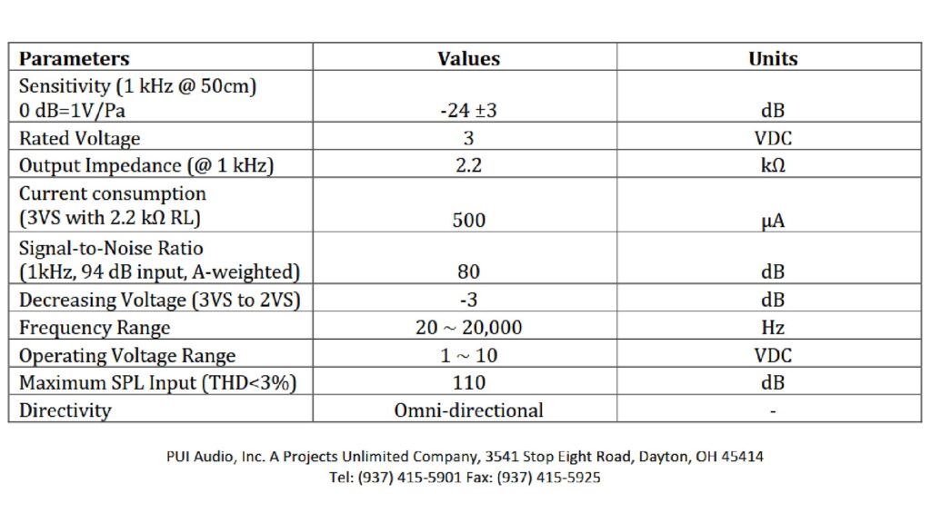
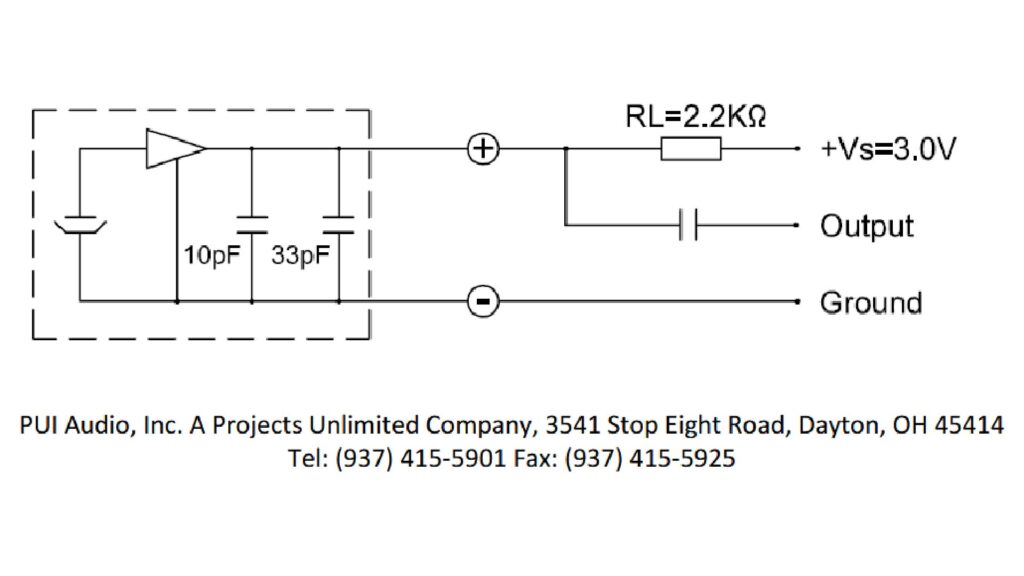
By the way, see my post on the 4 key microphone specifications and why they’re important if you want to know more about the most important parameters listed in the table of Figure 2.
Note that the table quotes an output impedance of 2.2K, and that the recommended circuit (which is the same unbalanced PiP circuit shown to the left of Figure 1) includes a load resistor of the same 2.2K.
Regarding bias voltage, the “operating voltage range” is specified at 1—10V. That’s a huge range, and in fact most ECMs can produce a useful signal over a pretty wide range of bias voltages (which is why PiP works at all).
However, the “rated” bias voltage is 3 VDC. This means that 3V is the only bias voltage (and 2.2K is the only load resistance) at which the AOM-5024’s impressive specs are guaranteed to be met.
And the specs give almost no information about performance at bias voltages or load resistances other than the rated values. The only such info is given by the somewhat ambiguously worded parameter “decreasing voltage from 3V to 2V”, which is quoted as “-3 dB”. This refers to the sensitivity, which is nominally specified as -24 dBV/Pa. That’s already a relatively high sensitivity for an ECM, so if a sensitivity reduction to -27 dBV/Pa were the only impact of a 1V decrease in bias voltage, it would be no big deal.
But that’s not the only effect of a non-optimum bias voltage or load resistance. Fortunately, a JFET buffer is a very simple device, so it’s pretty easy to see what happens when the voltage or load resistance change.
JFET buffer operation
The JFET buffer acts as a voltage-controlled current source: the current is controlled by the output voltage of the electret diaphragm (which varies with the incident sound pressure), and is then converted into the element’s output voltage by producing a voltage drop across the load resistor:
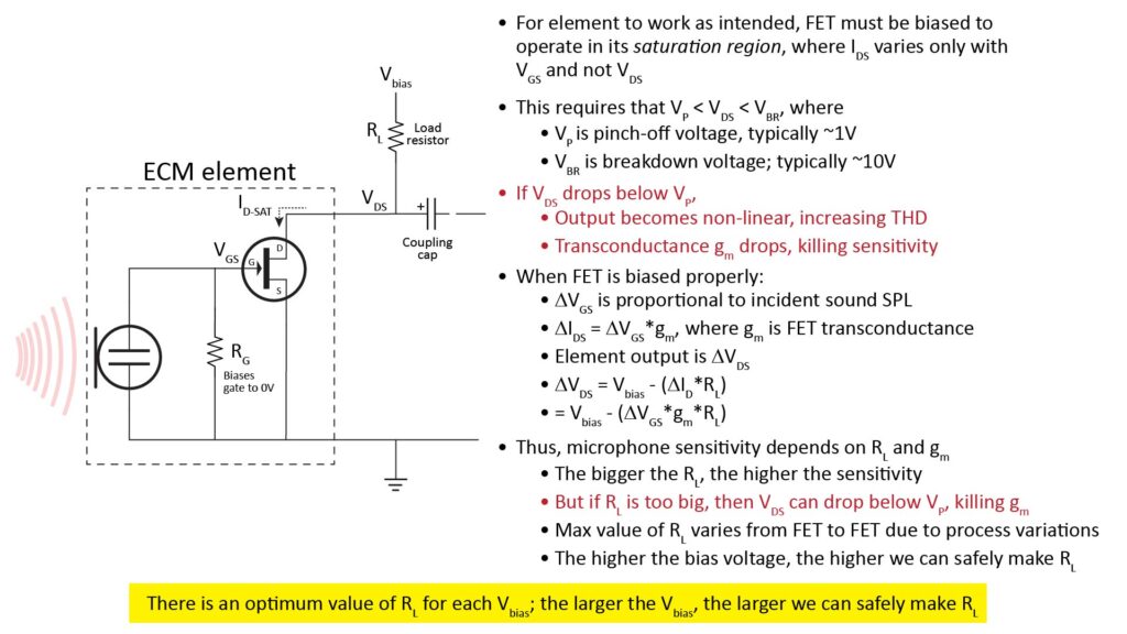
Notice that the drain-to-source voltage VDS, which varies inversely with the voltage drop across the load resistor RL, is the microphone element’s output signal. So, if we want the buffer to operate linearly, the drain current ID must vary only with the gate voltage VGS (which is due to sound reaching the diaphragm), and not with VDS (which is supposed to be the output). Otherwise, there would be feedback that would reduce the buffer’s gain (and make it non-linear, causing harmonic distortion).
This means that the drain-to-source path of the JFET cannot act like a simple resistor, but must instead act like a constant-current source. This requires that we bias the JFET to operate in the so-called saturation region.
JFET biasing for proper operation
Operation in the saturation region requires that VDS be kept comfortably above a voltage known as the pinchoff voltage, VP. On the other hand, VDS must also be less than the JFET’s breakdown voltage VBR, or else the mic element will stop working (and the JFET will possibly be damaged).
When the JFET is operating in the saturation region, there will be a reasonably constant drain current for a given VGS (regardless of changes in VDS) which is what we want for good gain and linear operation.
The behavior described above is illustrated in the following plot for a typical JFET:
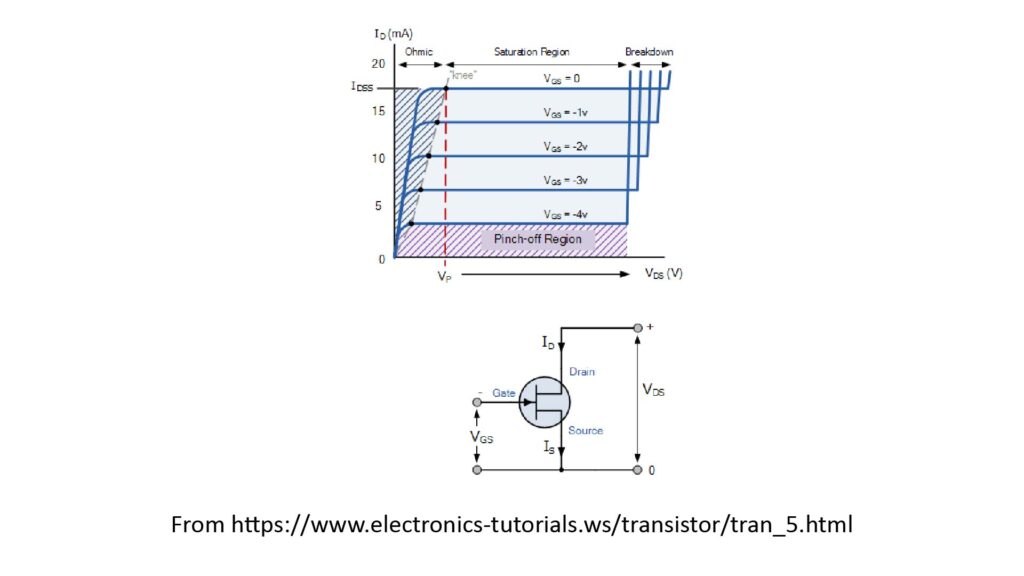
Note that the maximum drain current IDSS occurs for VGS=0; in other words, IDS decreases with increasing VGS. This maximum drain current IDSS is very important for proper biasing, because it determines the maximum value of load resistance RL for a given supply voltage Vbias to keep the JFET in saturation.
To attach some numbers to this discussion, let’s again consider the specs of the AOM-5024 as shown in Figure 1:
- The “operating voltage range” is quoted as 1—10V; the lower limit presumably corresponds to VP and the upper limit to VBR. This is typical; many ECM JFETs have a VP of the order of 1V and a VBR of the order of 10V.
- The “operating current” is quoted as 500 μA; this is the IDSS at the recommended operating point.
With the recommended supply voltage of 3V and load resistance of 2.2K, a 500 μA ID would drop 1.1 V across the load resistor, yielding a VDS of 1.9 V. This is the VDS—and the only VDS—at which the AOM-5024’s specs are guaranteed.
Device-to-device variation in JFET characteristics
A major issue with proper biasing of ECM JFETs is that the two key biasing parameters—VP and IDSS—can vary significantly from unit to unit of the same part number (as well as with temperature). Unfortunately, ECM (and JFET) manufacturers don’t provide much information on the statistics of this variation.
From my own experience and what I’ve been able to glean on the internet, a part to part variation in VP of 0.5V, and in IDSS of 33%, isn’t uncommon.
However, the manufacturer’s recommended bias voltage and load resistance is supposed to take this part-to-part variation into account. This is presumably why, for the AOM-5024, the spec sheet quotes an operating voltage down to 1V, but the recommended circuit implies a VDS of 1.9V with the quoted operating current of 500 μA. This provides a 0.9V “cushion”, mitigating the effects of part-to-part variations.
What happens with different PiP voltages and load resistances
Now that we’ve discussed microphone Plug-in Power (PiP) and the associated FET biasing requirements, we can examine the effect of varying PiP voltages and load resistances.
The main risk associated with uncertainty in PiP voltage and load resistance is that the JFET VDS could approach and even drop below VP, causing a sharp loss of sensitivity and increased Total-Harmonic Distortion (THD) due to non-linear operation. The following general rules apply:
- If the actual bias voltage is less than the manufacturer’s recommended bias voltage, then the load resistance must be less than the manufacturer’s recommended load resistance to keep the JFET in saturation.
- If the actual load resistance is greater than the manufacturer’s recommended load resistance, than the bias voltage must be greater than the recommended bias voltage to keep the JFET in saturation.
Minimum required bias voltage versus load resistance
One way to look at JFET buffer biasing requirements is to plot the minimum bias voltage, as a function of load resistance, necessary to keep VDS above a desired value (assuming we know the JFET’s IDSS). For example, the following chart shows the minimum required bias voltage to keep VDS above 1.9V as a function of load resistance, for three values of IDSS (the AOM-5024’s recommended IDSS of 500 μA plus or minus 100 μA):
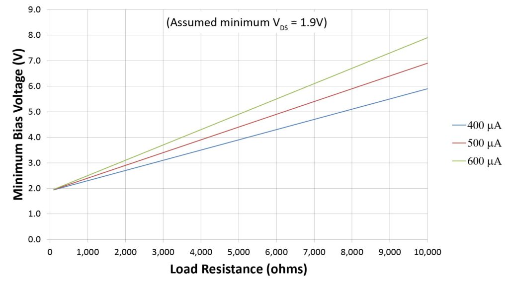
Obviously, the greater the bias voltage, the more operating “headroom” the buffer has above VP, and the greater the value of load resistance that can be used (of course, the bias voltage must not exceed the FET’s breakdown voltage VBR):
- At the manufacturer’s rated operating voltage of 3V, the maximum load resistance to keep VDS above 1.9V is the manufacturer’s recommended value of 2.2K.
- If the voltage is increased to 6V, the maximum load resistance increases to 8.2K.
As we’ll see in the next section, the load resistance determines the JFET buffer gain—and, hence, the microphone sensitivity.
Microphone sensitivity versus load resistance
Some PiP supplies with a relatively low bias voltage use a relatively low value of load resistance to try to ensure that VDS stays comfortably above VP. However, the JFET buffer gain is directly proportional to the load resistance, so reducing the PiP load resistance directly reduces the microphone element’s sensitivity.
For example, the AOM-5024 has a rated sensitivity of -24 dBV/Pa, which is based on the recommended load resistance value of 2.2K. Since the buffer gain varies directly with the load resistance, we can plot the effective sensitivity as a function of load resistance:
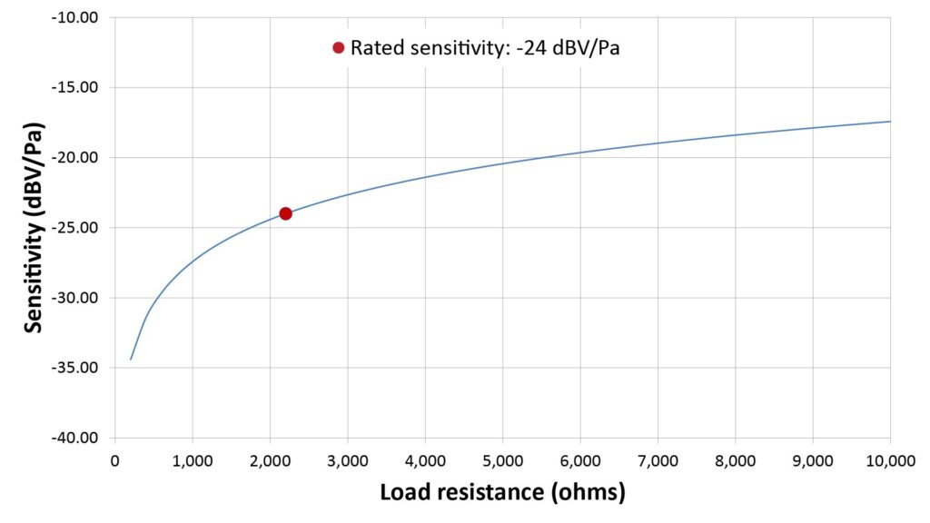
Note that per Figure 6, if we increased the bias voltage to 6V, we could increase the load resistance to 8.2K, which (per Figure 7) would result in a sensitivity of about -18.3 dBV/Pa—an increase of 5.7 dB over the manufacturer’s rated sensitivity.
On the other hand, a PiP supply with a load resistance of 1.1K would result in a 3 dB loss in sensitivity with respect to the manufacturer’s recommended 2.2K load resistance. Fortunately, PiP supplies are unlikely to have load resistances much less than 1K. And a 3 dB loss is relatively minor, especially in an element with such a high rated sensitivity as the AOM-5024. However, it’s still noticeable, and the loss could be much more significant with elements that have a lower rated sensitivity or a higher recommended value of load resistance.
Sensitivity or gain versus supply voltage
From the preceding discussion it’s evident that a greater supply voltage allows use of a greater load resistance for the same VDS, which in turn increases the buffer gain and hence microphone sensitivity. This suggests that the optimum PiP supply voltage is as high as possible without exceeding the JFET’s breakdown voltage.
For example, the following chart shows the relative buffer gain versus bias voltage for the AOM-5024, assuming that we’re using the largest load resistance that will keep VDS at the optimum 1.9V implied in the spec sheet:
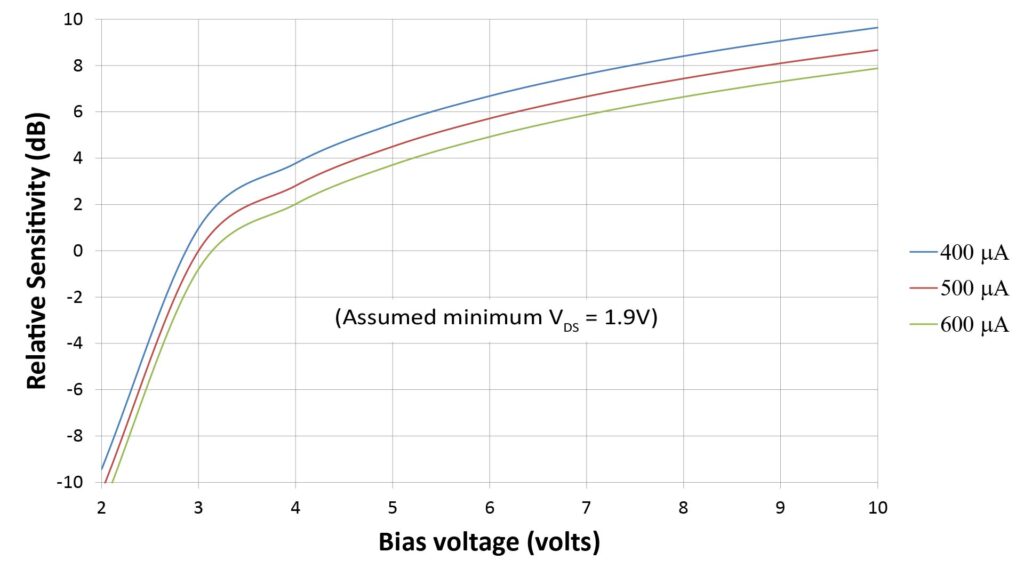
This shows that we can get 3 dB greater sensitivity by increasing the bias voltage from 3V to 4V. That’s probably not a big deal for an element that’s already quite sensitive (like the AOM-5024), but could be significant for lower-sensitivity elements.
Use caution when increasing the supply voltage and load resistance!
While increasing the supply voltage and load resistance of an ECM’s JFET buffer increases the sensitivity, it also reduces the circuit’s tolerance to part-to-part variations in IDSS: if the load resistance is doubled, the tolerance to variations in IDSS is halved. For this reason, it’s best to keep the load resistance reasonably close to the manufacturer’s recommended value, or else optimize the load resistance for each microphone element (and not just each microphone element part number). Also, because IDSS increases with temperature, the optimization should be done at the highest expected operating temperature.
Using microphone Plug-in Power with other Electret Condenser Microphone (ECM) elements
The previous discussion referenced the AOM-5024 because it’s one of my favorite ECM elements, but its susceptibility to performance degradation due to a mismatched PiP supply is qualitatively the same for other ECMs.
I’ll address specific PiP requirements for other microphone elements in an upcoming post.
Using microphone Plug-in Power for devices other than ECMs
Some ECM-based DIY microphones can benefit from active circuitry such as summing amplifiers and active filters, and Micro-Electro-Mechanical Systems (MEMS) microphone elements are often attractive alternatives to ECM elements.
Unfortunately, PiP is even more disadvantageous for MEMS-based microphones and those that incorporate active circuitry than it is for ECMs. The main issue is the limited current capacity due to the relatively high load resistance.
It certainly is possible to power a MEMS element from PiP (see Invensense Application Note AN-1181 [1] for a discussion of how to do it and the risks thereof), but it’s not a good idea if you care about performance.
Is Plug-in Power limiting the performance of your microphone?
If your PiP-powered microphone seems to have abnormally low sensitivity or high noise, or if its output seems a bit distorted, then a non-optimum PiP supply could be the culprit.
However, even if the output seems to sound fine, a non-optimum PiP supply could still be limiting its performance: the sensitivity, dynamic range, and signal-to-noise ratio could be lower than it would be with an optimized supply.
If anything less than maximum performance (even if you can’t immediately hear the difference) is unacceptable to you, then you might want to measure the voltage across the microphone element. That’s easy to do with a DIY breakout cable, like the one shown below:
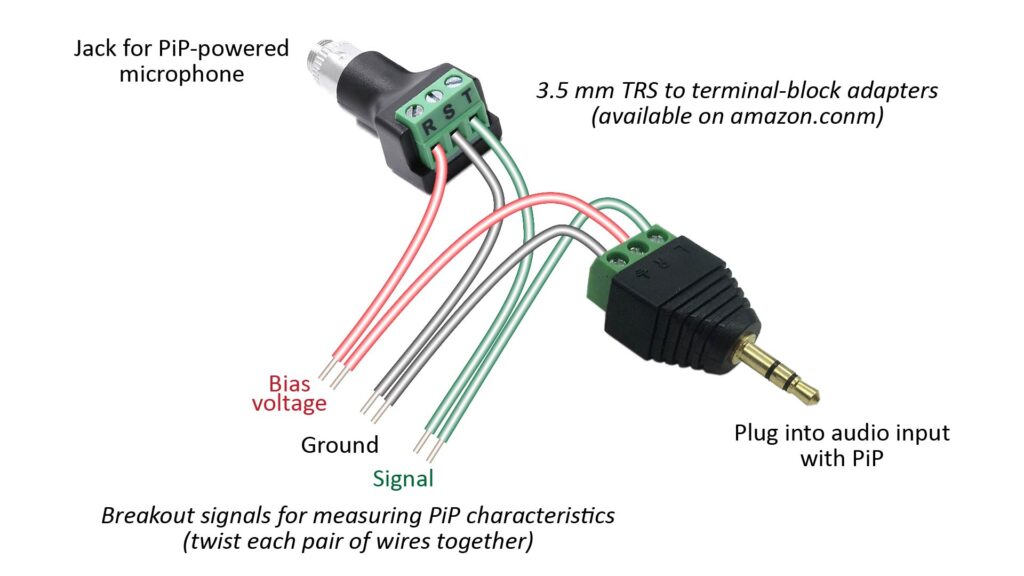
With the mic plugged into the breakout jack and the breakout plug plugged into the PiP-enabled audio input, the voltage across the bias-voltage and ground wires is the voltage across the microphone element. If this voltage is significantly lower than the microphone element’s specified operating voltage (if you know it)—or, if you don’t know the specified operating voltage, if it’s much lower than 1.5 V—then the PiP supply is probably limiting the microphone’s performance.
Mitigating the limitations of microphone Plug-in Power
There are two ways to mitigate the potential limitations of PiP:
- choose an ECM element based on the PiP characteristics of a specific audio device; or
- avoid PiP entirely by using another (optimized) power supply.
Choosing an ECM element for compatibility with a microphone Plug-In Power supply
If you’re building a microphone that needs to work only with a particular PiP-capable device, then you can choose a ECM element that will work well with the PiP provided by that device.
However, that microphone won’t be able to contain any power-consuming active circuitry other than the ECM itself (because of the limited current capacity of PiP supplies), and it won’t necessarily work well with any other audio device that supplies PiP.
To do this, you need to determine the PiP bias voltage and load resistance. If you don’t have a schematic of the audio device in question, you can determine these values with a couple of simple measurements, as follows:
- To determine the PiP bias voltage, measure the the open-circuit (unloaded) voltage between the ring and ground terminals of the PiP jack. For example, if you’re using a DIY breakout cable like the one shown in Figure 9, plug the breakout plug into the PiP device and use a multimeter to measure the voltage between the bias and ground terminals (without a microphone plugged into the breakout jack).
- The load resistance can be determined in two ways (again, without a microphone plugged into the breakout jack):
- Paragraph 9.2 of the standard that governs PiP (IEC 61938) specifies that “short circuit current should be limited to 3A”. This implies that PiP supplies should be capable of handling a short between the bias voltage and ground. Thus, the load resistance can be determined by measuring the current between the bias and ground terminals (using a multimeter on the milliamp setting), and then dividing the previously measured bias voltage by the measured current.
- Alternatively (if you’re worried about shorting the bias and ground terminals), you can measure the voltage across a resistor of between 1K and 10K connected between the ring and ground terminals; the load resistance can then be determined as follows:
- PiP load resistance = Rx/Vx*(Vbias – Vx), where Rx is the value of the test resistor, Vx is the voltage across the resistor and Vbias is the previously-measured bias voltage.
You can then choose an ECM that has a recommended supply voltage and load resistance close to the measured values.
Using an optimized power supply
Just because a device provides microphone Plug-in Power (PiP) doesn’t mean a microphone has to actually use it. Many PiP-capable devices have a switch that disconnects both the PiP bias voltage and the load resistor(s), but such a switch isn’t absolutely necessary in order to use another power supply.
In fact, battery-powered microphones are often used with PiP inputs, and they don’t require PiP to be switched off in the host device. This can be done as follows:
- DC-blocking capacitors are used to isolate the ECM element’s supply from the host device’s PiP, and
- another output buffer (with a lower impedance) is added between the ECM’s built-in JFET and the downstream device to keep the PiP load resistor from excessively loading the JFET’s output signal.
The is shown in the following figure:
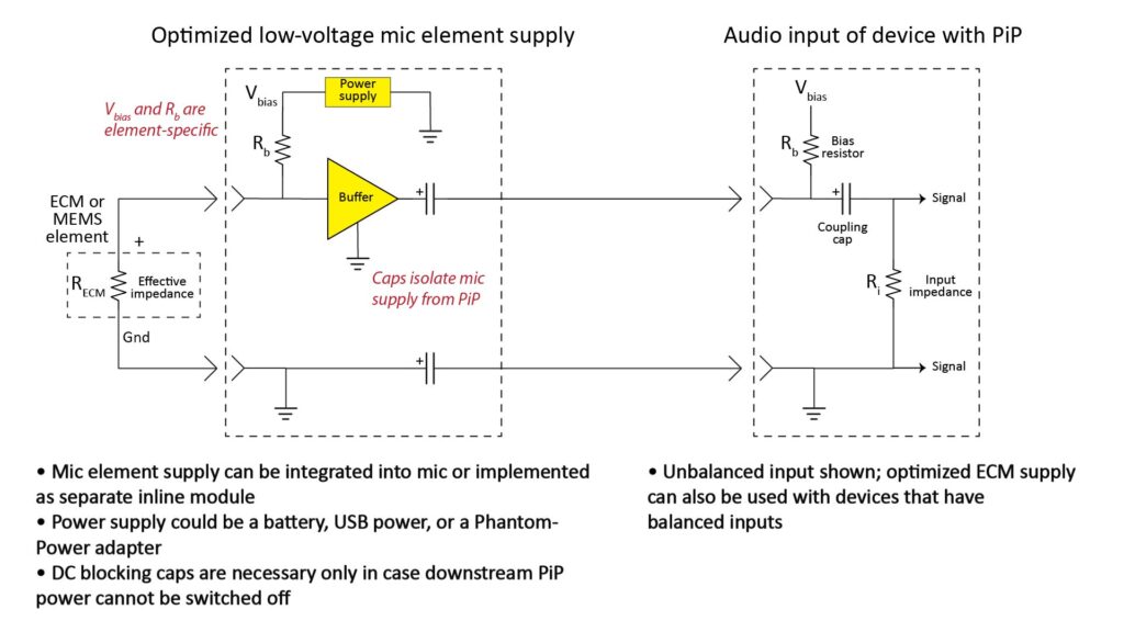
I’ll describe such an optimized power supply in more detail in an upcoming post.
The bottom-line: microphone Plug-in Power isn’t ideal for high-performance microphones
As we’ve seen, relying on microphone Plug-in Power (PiP) can be risky for three reasons:
- A PiP voltage lower than what the ECM manufacturer recommends can sharply reduce sensitivity and cause distortion. Unfortunately, the trend toward lower supply voltages for battery-powered devices makes this likely. A PiP load resistance greater than the manufacturer-recommended load resistance can cause the same problems.
- PiP can’t supply enough current to power anything but just an ECM element. So, a preamp, equalizer, summing amplifier, or other circuitry is usually out-of-the-question unless another power source is provided.
- While ECMs are extremely cost-effective, some DIY microphones are best implemented with Micro-Electro-Mechanical Systems (MEMS) elements. And PiP is even less ideal for MEMS elements than for ECMs.
So, if you care about performance and you’re using an audio recorder or other device with PiP with a powered microphone, it’s a good idea to:
- at least measure the PiP characteristics to make sure they’re compatible with the mic element;
- choose a mic element that *is* compatible with that particular device’s PiP characteristics; or
- avoid PiP entirely by using an optimized power supply (stay tuned for a post on that).
References
- A good video on powering ECM elements is Episode #611 of Dave Jones’ EEVblog [1], which features Doug Ford (former head designer at Rode Microphones) discussing the design of Electret Microphone Circuits. The YouTube channel is at https://www.youtube.com/c/EevblogDave while Episode #611 is at https://www.youtube.com/watch?v=UhG83WS51q8&list=PLvOlSehNtuHv98KUcud260yJBRQngBKiw&index=5 (accessed June 2022).
- Novoton’s Application Note AN-CS012 provides a brief discussion of the phenomenon of non-optimum PiP load resistances and bias voltages on ECM microphone performance: “Nuvoton CODECs and Electret Microphones,” available at https://www.digikey.com/Site/Global/Layouts/DownloadPdf.ashx?pdfUrl=E99C0AABB9F84CD286FB0F621593DC10 (accessed June 2022).
- Another potentially useful reference is Invensense Application Note AN-1181 [3], which describes how to power a MEMS microphone element with PiP: “Using a MEMS Microphone in a 2-Wire Microphone Circuit,” available at https://invensense.tdk.com/wp-content/uploads/2015/02/Using-a-MEMS-Microphone-in-a-2-Wire-Microphone-Circuit.pdf (accessed June 2022)