How exactly does a shotgun microphone exploit the principle of destructive interference, and how does shotgun microphone design determine performance? Read on for the most detailed explanation on the web.
- The purpose of a shotgun microphone
- Basic principles of shotgun microphone operation
- A shotgun microphone is a form of line microphone
- Modern shotgun microphones are actually hybrid microphones
- Not all microphones that appear to be shotgun microphones are shotgun microphones
- Advanced hybrid shotgun microphones
- This post is about true shotgun microphones
- Using the Traveling Wave Model (TWM) to explain line microphone operation
- Using the Traveling Wave Model to predict the performance of the Shure VP89L
- Limitations of the Traveling Wave Model in modeling shotgun microphone performance
- The three ground rules for shotgun microphone design
- Rule 1: inter-port spacing should be no greater than a quarter-wavelength at highest frequency of interest
- Rule 2: overall length should be no less than a half-wavelength at lowest frequency at which the line must maintain directivity
- Rule 3: overall length determines sharpness of main lobe (and directivity)
- Frequently-asked questions about shotgun microphones
- Why are some shotgun mics referred to as "line plus gradient" mics?
- Why do some shotgun mics mount the microphone halfway down the tube?
- Do "mini" shotgun microphones actually work?
- Can you improve the performance of a shotgun microphone by covering-up the slots?
- Can a shotgun microphone use a pressure microphone element?
- Is the length of a shotgun microphone included in its distance factor?
- Why don't shotgun microphones work well in a reverberant noise field?
- Is shotgun microphone self-noise important?
- How do shotgun microphones compare to parabolic microphones?
- How well do shotgun microphones really work?
- References
The purpose of a shotgun microphone
Today’s shotgun mic is the descendant of the “machine-gun” microphone that was developed during the early days of talking-picture movie production. Directors needed a new type of microphone that would be directional enough to be positioned just outside a camera’s field-of-view, and yet could capture voice with good fidelity while being easy enough to maneuver on-set.
And that’s still the purpose of today’s shotgun microphones: to suppress off-axis noise while capturing on-axis sound with good quality, in a package that’s as small, lightweight, and rugged as possible.
As most people familiar with shotgun microphones know, shotgun microphones don’t boost on-axis sound; their increased range comes purely from being more directional.
But how can a directional microphone provide greater range than a non-directional microphone if it doesn’t boost on-axis sound? It can’t—unless there is significant off-axis noise.
If there is significant off-axis noise, then when a microphone is moved further from a sound source, the Sound Pressure Level (SPL) of that sound drops, while the SPL of the off-axis noise typically doesn’t. The result is a reduction in the Signal-to-Noise Ratio (SNR) at the microphone output (where the noise includes acoustic ambient noise as well as microphone self-noise), reducing the sound quality.
So, making a microphone more directional decreases the noise SPL, improving the SNR at the microphone output—but there’s no improvement over a less directional microphone if there’s no off-axis noise.
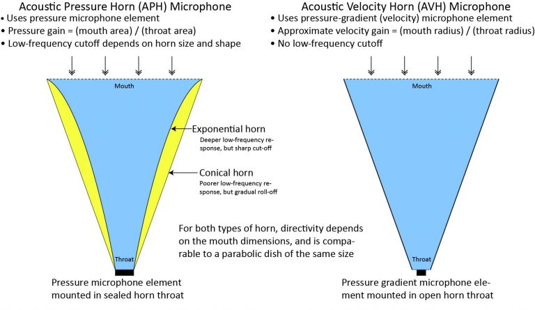
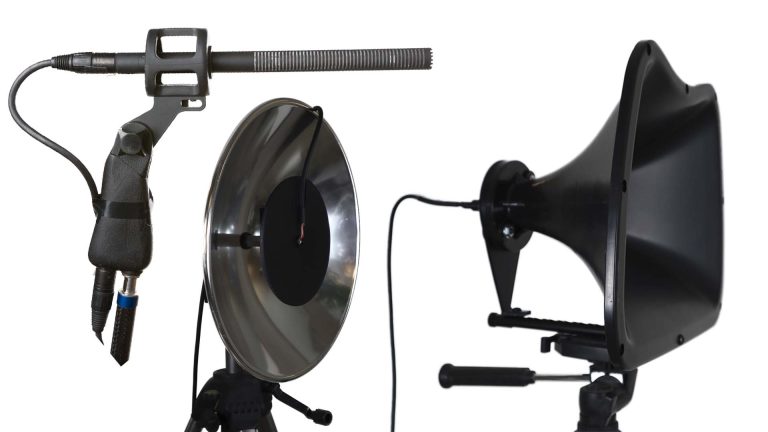
See my post on how long-range microphones work for more info on how directivity can increase pick-up range in the presence of ambient noise, and how shotgun microphones compare with other highly directional microphones. By the way, I also have detailed posts on how other types of highly-directional microphone work:
Basic principles of shotgun microphone operation
You’ve probably heard that a shotgun microphone achieves directionality through the principle of destructive wave interference. In this section, I’ll describe exactly what that means, and show how basic shotgun microphone design characteristics affect performance.
A shotgun microphone is a form of line microphone
A shotgun microphone is the most familiar example of a class of microphones known as line microphones, in which sound reaches a microphone element via multiple ports arranged along a line. The ports break up incident sound into separate components which recombine at the microphone element. For on-axis sound, the components reach the microphone at exactly the same time (in-phase), so they recombine constructively. However, for off-axis sound, the components arrive at the microphone element at slightly different times (with different phases), whereby they partially cancel through destructive interference.
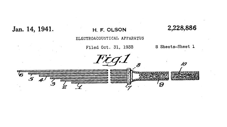
In the first line microphones (the previously-mentioned machine-gun microphones), the ports were the open ends of a cluster of tubes of varying length. In the modern shotgun microphone, the ports are holes or slots in the sidewall of a single interference tube (optionally, the front end of the interference tube itself is also open, providing another port). Check-out the history of the shotgun microphone if you want to see how the machine-gun microphone evolved into the modern shotgun microphone.
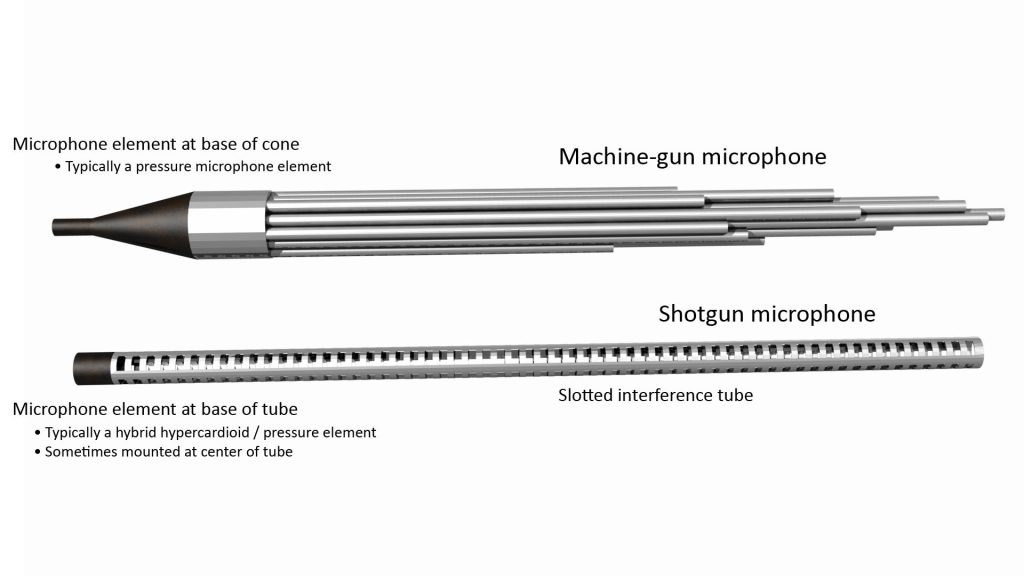
Although there are significant differences in appearance, machine-gun and shotgun microphones both work the same way, and the basic operating principle is quite simple.
Modern shotgun microphones are actually hybrid microphones
While the interference tube of a modern shotgun microphone is its most prominent feature, most high-performance shotgun microphones available today are actually two microphones in one.
Specifically, they operate as line microphones at higher frequencies, but as conventional cardioid, supercardioid, or hypercardioid microphones at lower frequencies (these standard polar patterns are discussed in more detail in the polar response section of my post on the 4 key microphone specifications).
High-performance shotgun microphones use a hybrid configuration because (as we’ll see later) the directivity of a line microphone depends on its length in wavelengths, and reasonably-sized line microphones provide little directivity at bass frequencies. That’s where the cardioid capsule comes into play.
Not all microphones that appear to be shotgun microphones are shotgun microphones
Because the directivity of a line microphone depends on its length in wavelengths, a physically short line microphone isn’t very useful.
And, yet, there are plenty of miniature “shotgun” microphones on the market. It turns out that these are not line microphones at all, but rather just conventional directional studio microphones packaged in a tubular form-factor. Such microphones are useful, but they can’t provide the high directivitity of the true shotgun microphones that are the subject of this post.
Advanced hybrid shotgun microphones
The advent of Digital Signal Processing (DSP) has also enabled more advanced versions of hybrid shotgun microphones. DSP enables Space-Time Adaptive Processing (STAP), a technique pioneered in military radar and sonar systems in which the outputs of multiple sensors are processed to dramatically increase the signal-to-interference ratio in the presence of off-axis noise.
So far, most consumer applications of STAP-enabled microphones have been for videoconferencing or speakerphone applications. I’m aware of only two shotgun microphones that use some kind of space-time adaptive processing: the Audio-Technica AT895 (now discontinued) and the Schoeps SuperCMIT. These use a line microphone in conjunction with at least another microphone capsule (a single auxiliary capsule in the case of the SuperCMIT, and four auxiliary capsules in the case of the AT895), along with a DSP to process the microphone outputs.
This post is about true shotgun microphones
Whether or not a hybrid configuration is used, what makes a true shotgun microphone a shotgun microphone is its interference tube, and that’s mainly what this post is about.
Using the Traveling Wave Model (TWM) to explain line microphone operation
One of the best ways to understand how something works is to try to model its performance. We can get a reasonably good idea of a line microphone’s performance using the relatively simple Traveling Wave Model (TWM).
Essentially, the TWM treats each port in a line microphone as an element in an array microphone (which I address in detail in my post on how array microphones work). The TWM assumes that the sound component entering each port propagates as a traveling wave before it reaches the microphone diaphragm. This means that the microphone output can be predicted solely on the basis of the amplitudes of, and phases between, the components when they reach the diaphragm, which determines the degree of destructive interference (and, hence, the polar pattern).
Simple two-port line microphone
To see how a line microphone works from the perspective of the TWM, let’s first consider the simplest possible implementation. This would be a line microphone which has just a pair of ports (which could be a pair of slots in a shotgun microphone, or a pair of tubes in a machine-gun microphone). Note that the ports in many actual interference tubes are round holes rather than rectangular slots, but the principle of operation is the same.
As shown in the attached figure, the ports split incident sound into two components that reach the microphone separately. Depending on the direction from which the sound arrives, the components can travel the same distance before reaching the microphone (for on-axis sound), or slightly different distances (for off-axis sound).
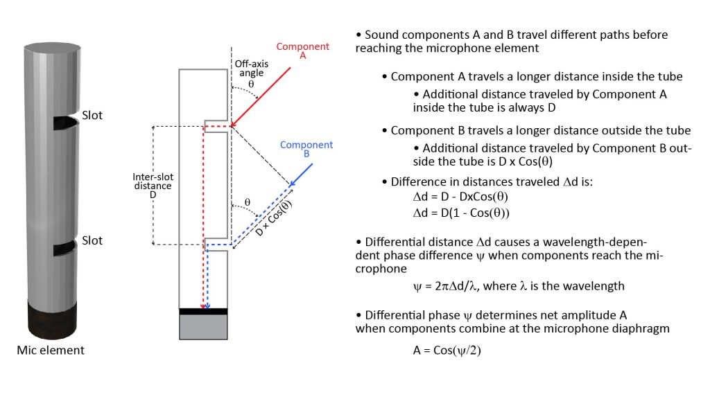
When the sound arrives on-axis (in other words, when the off-axis angle θ is zero), the difference in the distance traveled by the two components is also zero.
However, for off-axis sound, the components travel different distances before reaching the microphone element. For example, when θ is 90 degrees, the difference in distance is equal to the inter-slot distance D, and when θ is 180 degrees, the difference is 2D. We can generalize the difference in distance traveled by the two components as follows:
Δd = D[1-cos(θ)] (equation 1)
Let’s assume that the incident sound is a pure tone of wavelength λ. Then we can convert the distance difference Δd into a phase difference (in radians) between the two components, as follows:
ψ = 2πΔd/λ (equation 2)
Now that we know the phase difference, we can compute the relative amplitude A (normalized to unity) of the sum of these two components when they recombine at the microphone element, as follows:
A = cos(ψ/2) (equation 3)
Using the three equations above, we can express the recombined amplitude at the microphone element as a function of the inter-slot spacing D, the off-axis angle θ, and the wavelength λ. If we plot this amplitude versus off-axis angle θ, we get the polar amplitude or voltage pattern of the simple two-port microphone; if we plot the square of the amplitude, we get the polar power pattern, which is what is typically used to characterize a microphone’s directional characteristics.
The following figure shows plots of the power pattern in dB (obtained as 20logA) versus off-axis angle θ, for four different values of D ranging from D=λ/8 to D=λ, for the simple two-port microphone of Figure 3 above:
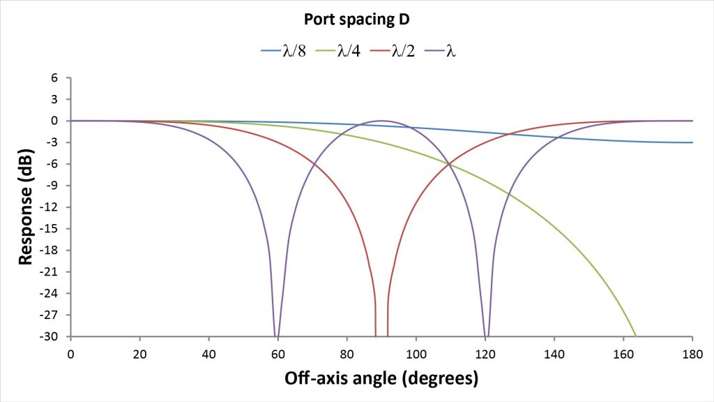
These plots illustrate three important facts about this simple two-port line microphone:
- There’s only one spacing at which there is a single on-axis mainlobe: D=λ/4. At this spacing there is complete cancellation at 180 degrees…but the mainlobe is very broad, with only 3 dB of rejection at 90 degrees. Such a broad cardioid pattern would be useful, but certainly wouldn’t be considered ultra-directional.
- If the spacing is reduced below D=λ/4, the rejection at 180 degrees decreases and the microphone starts to lose its directionality. In fact, at D=λ/8, the response at 180 degrees is down only 3 dB.
- If the spacing is increased above D=λ/4, the on-axis mainlobe starts to get sharper—but now there are other lobes of equal amplitude that spoil the directivity. When D=λ/2, the response is bidirectional, with lobes at both zero and 180 degrees. As the spacing continues to increase, the mainlobe gets sharper, but lobes at additional off-axis angles appear.
So this simple two-port microphone isn’t very useful: it provides a clean unidirectional pattern only at a single spacing/wavelength (D=λ/4), but that pattern is a broad cardioid pattern. And the microphone provides useful directivity over only a two-octave bandwidth: the rejection at 180 degrees is only 3 dB when D=λ/8, but the pattern becomes bidirectional when D=λ/2.
There’s also another problem we haven’t yet discussed: a two-port microphone will have two distinct resonant frequencies, which will affect the frequency response.
How do we fix these problems? We add more ports!
Adding more ports yields a useful line microphone
A practical line microphone has tens of ports, rather than just a pair of ports. For example, a modern shotgun microphone like the Shure VP89L has about 38 slots, while the original machine-gun microphone (the Western Electric 618A/E99098) had 50 tubes. By the way (as I’ve already mentioned), I have a post on the history of the shotgun microphone if you’re interested in how line microphones have evolved since their inception.
To see the effect of adding more ports, consider an N-port line microphone with an inter-port spacing of D, and assume that D is a quarter-wavelength. The output of such a microphone can be viewed as the superposition of the outputs of many virtual two-port microphones, each with a different effective inter-port spacing. In fact, there will be (N-1) different values of inter-port spacing:
- The shortest effective inter-port spacing will be D=λ/4, so the corresponding virtual microphone will have a cardioid pattern with a broad lobe at zero degrees.
- The longest effective inter-port spacing will be N*D, so the corresponding virtual microphone will have a narrower lobe at zero degrees (with the width reduced by a factor of 1/N), but will also have the same narrow lobes at angles other than zero degrees.
- If N is greater than three, there will also be at least one other inter-port spacing, with the corresponding virtual microphone having yet another different lobe width and structure.
The different polar patterns from all these virtual two-port microphones have one thing is common: they all have a lobe at zero degrees…but the lobes at angles other than zero degrees don’t line up.
So, when the components from the ports in an N-port line microphone are superimposed at the microphone element, the peak at zero degrees is unaffected, but the response at all other angles is reduced. Therefore, as N is increased, the mainlobe at zero degrees gets proportionally sharper, the lobes at other angles get smaller, the bandwidth over which the microphone provides useful directivity increases, and the frequency response gets smoother.
Modeling the polar pattern of an N-port shotgun microphone
When there are N-ports, rather than just two ports, we can’t use equation 3 above to calculate the relative microphone output. Instead we use the following Array Factor (AF) equation, which gives the absolute value of the amplitude of the superposition of N sinusoids with a differential phase of φ (which is the same φ from equations 1 and 2 above):
AF = Abs[sin(Nψ/2)/Nsin(ψ/2)] (equation 4),
Equation 4 is the same equation used to determine the output of an additive array microphone (or an array antenna) of N uniformly-spaced elements. By the way, I have a detailed post on array microphones if you’re interested in that topic. Anyway, the Array Factor AF represents the relative voltage response of a line or array microphone, so that 10log(AF) represents the relative voltage response in dB, while 20log(AF) represents the relative power response in dB (which is what is typically plotted in a microphone’s polar pattern).
So the TWM, as defined by equations 1, 2, and 4 above, requires only two design parameters to predict the relative response of an N-port line microphone at a given off-axis angle θ and wavelength λ:
- D, as previously discussed, is the inter-port spacing: either the spacing between the slots in an interference tube of a shotgun microphone, or the smallest difference in the tube lengths in a machine-gun microphone. Note that this formula assumes uniform spacing, so there is just a single value of D.
- N is the number of ports: either the number of slots in an interference tube of a shotgun microphone, or the number of tubes in a machine-gun microphone.
Obviously, such a simple formula (which neglects factors such as shotgun slot size and shape, machine-gun tube diameter, microphone acoustic impedance, etc.) can’t provide a very accurate prediction of line microphone performance…but it’s close enough to be useful. Let’s see if we can use the TWM to model the performance of an actual shotgun microphone.
Using the Traveling Wave Model to predict the performance of the Shure VP89L
The Shure VP89 is typical of today’s longer shotgun mics. It’s a modular microphone system that includes a preamplifer base that can accept one of three available “microphone capsules”, each of which includes an interference tube. Each of the three capsules has a different length, so the system offers a choice of three different polar patterns. Let’s try to model the version with the longest capsule, the VP89L.
First, let’s look at the polar patterns provided by Shure in the VP89 User Guide [1]:
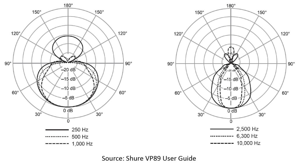
These are nice, clean polar patterns with just one main lobe at zero degrees, and at most two small rear-facing lobes. It’s not clear from the User Guide if these are supposed to be actual measured patterns, theoretically modeled patterns, or just notional patterns. But, in any case, these are the “official” manufacturer-supplied patterns.
As expected, the polar patterns become more directional with increasing frequency. I’m going to refer to several values eyeballed from these patterns later on for comparison with the results of our model, but for now that’s all we need to observe about these patterns.
The VP89 User Guide [1] also provides drawings of the microphone capsules, which we can use to estimate the VP89L capsule’s number of slots and their spacing:
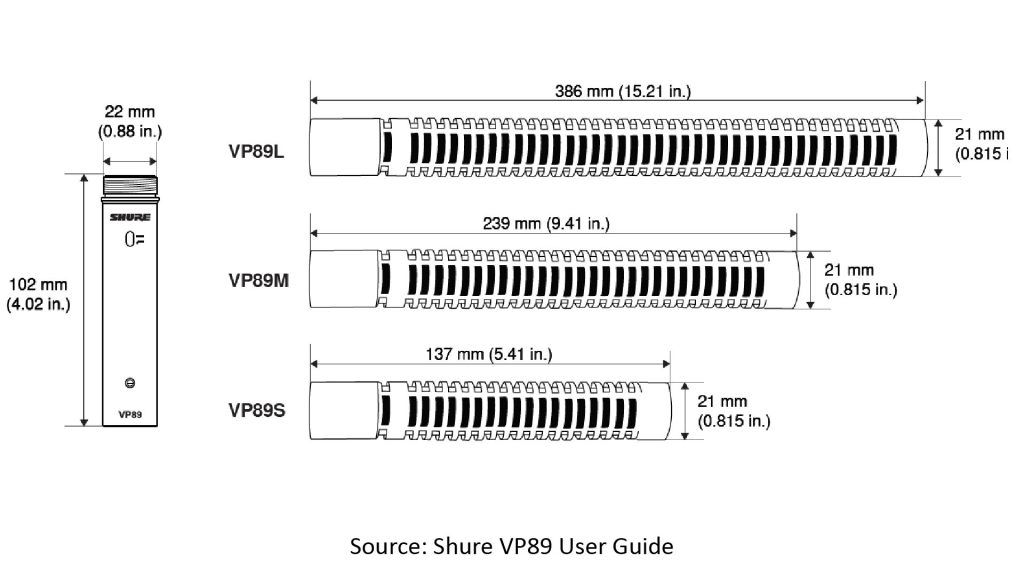
Notice that the slots are uniformly spaced, except for the slot closest to the base of each tube. The relatively large space between this slot and the next slot is where the cardioid-type microphone element is located, and the slot closest to the base is there to allow sound to reach the back of the microphone diaphragm (which is necessary for proper operation of a cardioid-type element). All modern shotgun microphones use a cardioid-type element (almost always a hypercardioid); we’ll see why later.
As the figure shows, the interference tube has 38 slots (other than the rear port for the microphone element), and based on the dimensions provided, I estimate the inter-slot distance D as about 0.3 inches.
That’s all the information we need to plug into our simple model. Let’s run it for four of the frequencies specified in the polar patterns provided by Shure (250 Hz, 2.5 kHz, 6.3 kHz, and 10 kHz).
The attached figure shows plots of our model-predicted microphone power response versus off-axis angle for those four frequencies, along with some data points I eyeballed from the Shure-provided polar patterns [1]:
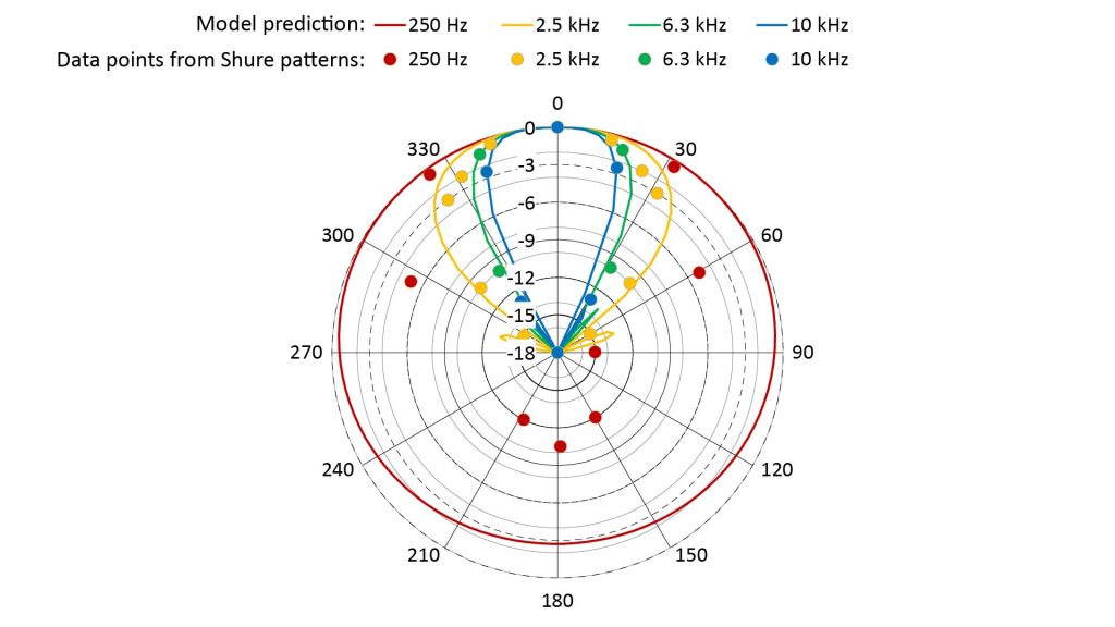
The model-predicted patterns match the Shure-provided data reasonably well at the higher three frequencies, but there is significant discrepancy at 250 Hz, where our model predicts a near-omnidirectional pattern.
However, this discrepancy isn’t due to a problem with our model, but rather to the fact that the VP89 isn’t just a line microphone; it’s a combination of a line microphone and a hypercardioid microphone.
In fact, the poor low-frequency directionality predicted by our model accurately reflects one of the issues with pure line microphones: they’re directive only down to the frequency corresponding to a wavelength of 2L, where L is the length of the line (which is effectively the length of the interference tube in a shotgun microphone, or the maximum tube-length difference in a machine-gun microphone). This frequency is known in line microphone terminology as the critical frequency.
Since the VP89L’s interference tube appears to be about 12 inches long, the critical frequency is about 550 Hz. That’s why our model indicates such poor directivity at 250 Hz.
If it were a pure line microphone, the VP89L would need an interference tube about 36 inches long to provide the claimed directivity at 250 Hz. Instead, it uses the compound line/cardioid approach originally invented by Wayne A. Beaverson and Robert C. Ramsey 60 years ago (U.S. patent 3,095,484), and first used commercially in the Electro-Voice Cardiline Model 642 shotgun microphone around 1960 (see my post on the history of the shotgun microphone for more detail).
The Cardiline microphones, as suggested by the name, were both cardioid microphones and shotgun-type line microphones. They consisted of a cardioid microphone element mounted behind an interference tube, and incorporated acoustic filters to roll-off the microphone element’s response at high frequencies and the interference tube’s response at low frequencies. The filter crossover frequency was chosen to be at or above the interference tube’s critical frequency.
As far as I know, all of today’s commercially available shotgun microphones—including the VP89L—use the same principle. Since the VP89L’s critical frequency appears to be around 550 Hz, the crossover to the hypercardioid capsule would have to be well above the 250 Hz frequency at which our model results differ from the Shure data. And the Shure-supplied pattern at 250 Hz looks very much like a hypercardioid pattern.
Thus, the low-frequency discrepancy is almost certainly due to the presence of hypercardioid capsule.
Limitations of the Traveling Wave Model in modeling shotgun microphone performance
The simple TWM is a useful tool for understanding how shotgun and machine-gun microphones work, and it’s even accurate enough to provide useful approximations of their polar patterns for design purposes. In fact, I’ve used it to design line microphones that work pretty well—but that’s a subject for another post.
However, there are significant second-order phenomena in the operation of line microphones (and particularly shotgun microphones, which are more complex than machine-gun microphones) that aren’t addressed in the simple TWM described above. If you were a manufacturer of shotgun microphones costing a thousand dollars, you’d certainly want to use a more sophisticated design model that comprehends some of these second-order phenomena.
For example, we’ve assumed that all of the port components arrive at the microphone element with the same amplitude, differing only in phase. This is a reasonable assumption for the purposes of explaining shotgun microphone operation, but not for actually designing a high-performance shotgun microphone.
In a real interference tube with equally-sized ports, the amplitudes of the port components do differ significantly in amplitude when they arrive at the microphone element. This is because the ports don’t just admit sound into the tube; they also allow sound to leak out of the tube. Thus, the further a port is from the microphone, the weaker its component will be.
This amplitude imbalance reduces the destructive interference of off-axis sound and degrades the sharpness of the polar pattern.
Modern shotgun mics mitigate this effect by varying the areas of the ports along the tube, or by adding damping material whose attenuation varies along the length of the tube. Amplitude imbalance is much less of an issue with a machine-gun mic, but does exist and can be mitigated if desired by varying the tube diameters.
Other phenomena that aren’t comprehended in the TWM are the presence of standing waves or diffraction effects.
A good discussion of the limitations of the TWM in modeling shotgun mic performance (and some proposed modeling improvements) are presented in the 2013 paper by Bai and Lo [2].
The three ground rules for shotgun microphone design
Even if you’re not actually designing shotgun microphones, knowing the three ground rules of shotgun microphone design can give you a better understanding of how they work (and what to buy).
If you’ve studied the simple Traveling Wave Model of line-microphone operation described above, you probably already know the three ground rules, but here they are anyway:
- The inter-port spacing D should be no greater than a quarter-wavelength at the highest frequency of interest.
- The overall length of the line, equal to (N-1)*D where N is the number of ports, should be no less than a half-wavelength at the lowest frequency at which the line must be directional.
- The overall length of the line also determines the mainlobe sharpness: the longer line, the more directional the microphone. So the greater the required range, the greater the required directivity and the greater the required line length.
Rule 1: inter-port spacing should be no greater than a quarter-wavelength at highest frequency of interest
As we saw earlier in this post, a simple two-port line microphone provides a clean unidirectional polar pattern only up to the frequency at which the spacing is a quarter-wavelength (λ/4). Above that frequency, spurious full-amplitude lobes (known as grating lobes) appear at off-axis angles.
Per the Traveling Wave Model, this is also true for an N-port line microphone. So, if we want to keep grating lobes out of the microphone’s polar pattern at frequencies up to 10 kHz, then D can be no greater than about 0.33 inches. Perhaps not coincidentally, this also happens to be the apparent inter-slot spacing for the VP89L’s interference tube.
But what happens if we make D less than λ/4 at the highest frequency of interest? According to our simple Traveling Wave Model, the directivity will decrease, so there is no apparent benefit to using a smaller slot spacing than necessary.
However, more sophisticated models that also consider slot size and shape could indicate an optimum value of D that’s smaller than λ/4.
Rule 2: overall length should be no less than a half-wavelength at lowest frequency at which the line must maintain directivity
The lowest frequency at which a pure line microphone will provide useful directivity is called the critical frequency. The critical frequency is determined by the length L of the line (where L is the length of the interference tube in a shotgun microphone, or the difference in length between the shortest and longest tubes in a machine-gun microphone). You might have heard that the critical wavelength is equal to 2L, which means that the critical frequency is equal to c/2L, where c is the speed of sound.
But from our previous discussion of the TWM, we know that the greatest differential distance traveled by the components from any pair of ports in a line microphone (which occurs at an off-axis angle of 180 degrees) is twice the distance between the ports.
So, at the so-called critical wavelength of 2L, the differential distance traveled by the closest and furthest ports will be one wavelength at 180 degrees. Thus, there will be no cancellation at 180 degrees, resulting in a bidirectional pattern.
A bidirectional pattern certainly isn’t the kind of directivity we want from a shotgun mic, so how can it be said that a shotgun microphone is directive down to a wavelength of 2L?
The answer lies in the fact that all practical shotgun microphones use many ports, not just two ports, and the output is the superposition of the components from all the ports. So, while interference between just the components from the closest and furthest ports tends to cause a full-amplitude lobe at 180 degrees, the superposition of all the components ensures that there is, in fact, a single (albeit broad) lobe pointing at zero degrees when λ=2L.
And that’s why a pure line microphone provides usable directivity down to a critical wavelength of 2L. Of course, we can get useful directivity at even longer wavelengths by using some type of cardioid capsule, like the VP89L (and other modern shotgun microphones).
Rule 3: overall length determines sharpness of main lobe (and directivity)
As we’ve discussed, the mainlobe in a line microphone gets sharper with increasing line length.
Of course, if we increase the line length without also increasing the number of ports, then the inter-port spacing would also increase, giving rise to spurious off-axis lobes (per Rule 1 above). This could offset any directivity advantage of a sharper mainlobe.
Fortunately, as we’ve already observed, if we increase the line length by increasing the number of ports (keeping the inter-port spacing constant), then we get both a sharper mainlobe and better off-axis rejection.
But what exactly is the relationship between line length and mainlobe width? We can certainly determine the mainlobe width of a line microphone by plotting the polar response using the Traveling Wave Model described above.
Alternatively, there are some simple formulas developed by radar engineers that we can use to quickly estimate the mainlobe width of a line microphone. We can estimate both the First Null BeamWidth (FNBW) and the Half-Power BeamWidth (HPBW), which are two of the most frequently used metrics to quantify the sharpness of a directional device’s polar pattern.
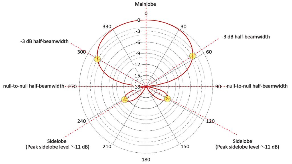
First Null BeamWidth (FNBW) and Half-Power BeamWidth (HPBW)
Every line microphone with multiple ports (or any type of array sensor with multiple elements) has at least two nulls, one on either side of a mainlobe. The First Null BeamWidth (FNBW) is the angular distance between the nulls that spans the mainlobe, while the Half-Power BeamWidth is the width of mainlobe between the points where the power response has fallen by 3 dB relative to the peak:
We could find the FNBW or the HPBW of a line microphone by setting the Array Factor amplitude (given previously in equation 4) to either 0 or 0.707, respectively, and solving for the angle. But according to the TWM, a line microphone behaves like an additive array microphone steered to the end-fire direction, so we can use the corresponding equations that have already been developed for additive arrays:
- FNBW (in radians) = 2*sqrt(λ/L) (equation 5), and
- HPBW (in radians) = 2*sqrt(0.866λ/L) (equation 6), where L is the line length and λ is the wavelength.
Directivity
The directivity of a microphone is the ratio of its on-axis sensitivity to its sensitivity averaged over all directions. It’s usually expressed in dB as the Directivity Index (DI), which is equal to 10log(directivity). So a microphone with an isotropic polar pattern would have a DI of 0 dB, while a hypercardioid studio microphone has a DI of 6 dB.
A microphone’s DI can be estimated from its beamwidth. However, for a line microphone, there’s an even simpler way to estimate the DI: assuming a quarter-wavelength slot spacing and an overall line length much greater than the slot spacing, DI = 10log(4L/λ) , where L is the line length and λ is the wavelength. For a shotgun microphone that integrates a hypercardioid capsule, the directivity can then be found as the greater of 6 dB and the DI of the interference tube, like this:
- DI = Max(6 dB, 10log(4L/λ)) (equation 7)
Unfortunately, there don’t seem to be any official directivity specifications for the VP89L on the web, but I do have a hardcopy of an official VP89L directivity curve on-hand. The following figure plots some data points I eyeballed off that curve against the DI obtained using the simple equation above:
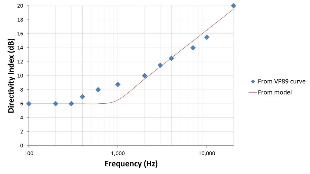
So, despite the simplicity of equation 7, it yields directivity projections that agree reasonably well with the official numbers.
By the way, as with our simple TWM, all of these beamwidth and directivity equations assume uniform port spacing and equal port amplitudes.
Frequently-asked questions about shotgun microphones
Now that we know how line microphones work, we can answer some questions that frequently come up (at least according to my own research) about shotgun microphones.
Why are some shotgun mics referred to as “line plus gradient” mics?
Like the Shure VP-89L discussed above, most shotgun microphones today combine an interference tube with some type of cardioid microphone capsule. The term “line plus gradient” is often used to describe such a configuration: “line” refer to the interference tube, and “gradient” (short for pressure-gradient) is supposed to refer to the microphone capsule, which has a cardioid, supercardioid, or hypercardioid pattern.
However, this usage isn’t technically correct because a true pressure-gradient microphone has a bidirectional—not a cardioid-family—pattern. A microphone that has a cardioid-family pattern is actually a hybrid of a pressure microphone and a pressure-gradient microphone.
However, pressure-gradient and cardioid microphone capsules do have one thing in common: they both require sound to be able to reach both sides of their diaphragms for proper operation. And that probably accounts for the use of the word “gradient”.
Why do some shotgun mics mount the microphone halfway down the tube?
In our discussions so far, we’ve assumed that the microphone element is mounted at the end of the interference tube. However, in some commercial shotgun mics, the microphone element is actually mounted halfway down the tube. Why is this?
This would make no sense if an isotropic (pressure-type) microphone element were used. However, most modern shotgun microphones use a form of cardioid element, and putting the cardioid element halfway down the tube balances the acoustic impedances on both sides of the diaphragm, presumably helping to smooth-out the frequency response. Of course, this also halves the effective line length, doubling the mainlobe beamwidth.
Further, mounting the microphone halfway down the tube isn’t the only way to ensure a balanced acoustic impedance across the diaphragm. However, it’s probably the easiest in terms of design effort.
Do “mini” shotgun microphones actually work?
Shotgun microphones have become a meme: most people who aren’t familiar with microphones automatically infer that a skinny tubular microphone should be able to pick up sound at a greater range than microphones of other shapes.
But if you’ve read the preceding material, you know that a true shotgun microphone’s increased range isn’t due to its shape, but rather to its use of an interference tube to provide high directivity. You also know that an interference tube’s directivity depends on its length.
In fact, an interference tube shorter than about 6 inches provides less useful directivity at voice frequencies than a studio microphone with a cardioid pattern.
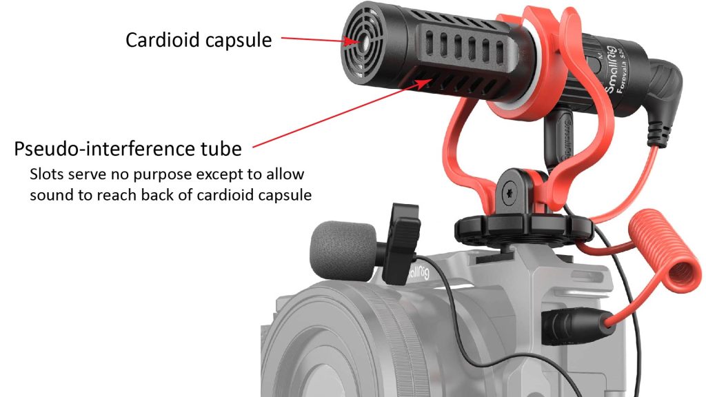
And, yet, there are many “shotgun” microphones on the market that are much shorter than that. But while these look like shotgun microphones (with a tubular shape and slots along their length), they aren’t, in fact, true shotgun microphones because their tubular housing isn’t actually an interference tube. Most such pseudo-shotgun microphones fall into two categories:
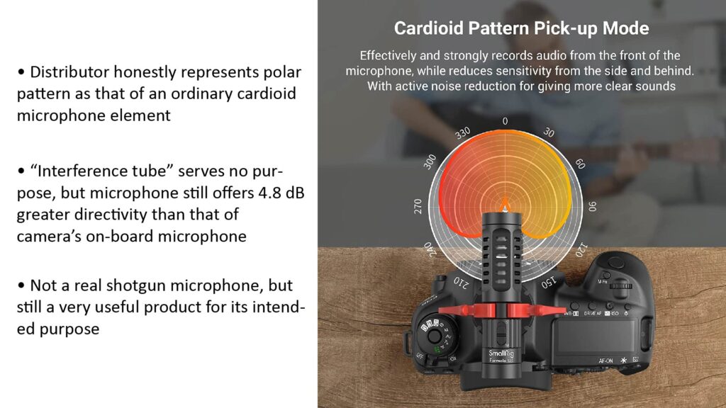
- Microphones that have a fixed cardioid pattern. These consist of an ordinary cardioid microphone capsule mounted at the front of a short tube (rather than at the back or middle of the tube, where it should be in a real shotgun mic). In this case, any slots in the tube are purely decorative.
- Microphones that have a pattern that’s switchable between at least two cardioid-family patterns (typically cardioid and supercardioid). These usually include two microphone elements (one mounted near the front of the tube and the other mounted near the back of the tube), as well as some electronics to process the outputs of the elements to yield the desired pattern. In this case, the slots in the tube are necessary so that incoming sounds can reach both elements, but they provide no destructive interference of off-axis sounds. Such microphones work like two-element array microphones, which I discuss in detail in my post on how array microphones work.
So, both of these types of “shotgun” microphone aren’t shotgun microphones at all, but rather cardioid-pattern microphones in a tubular form-factor.
Do such pseudo-shotgun microphones “work”?
Yes, in the sense that a cardioid pattern is more effective than an isotropic pattern at suppressing off-axis sound.
And the fact that such microphones are designed to look like shotgun microphones isn’t really false advertising, for two reasons:
- A true interference tube of such a short length would provide no additional benefit, since its directivity would be less than that of cardioid pattern.
- Most manufacturers of such microphones clearly state that their polar patterns are of the cardioid type.
Can you improve the performance of a shotgun microphone by covering-up the slots?
The answer to this should be obvious by now: NO!
However, if you don’t know how shotgun microphones work, you might think that the slots are there to make the microphone less directional by intentionally admitting off-axis noise, which of course isn’t true. The slots are actually what make a shotgun microphone directional, because without them, there wouldn’t be any destructive interference of off-axis noise.
But how about covering-up some of the slots with gaffer’s tape to adjust the directionality to suit the circumstances? For example, wouldn’t covering up half the slots be useful to make the microphone easier to aim when there isn’t much off-axis noise?
That’s not a good idea, either. It’s true that you can indeed reduce a shotgun mic’s directivity by covering-up some of the slots. But one of the benefits of having multiple slots along an interference tube is to attenuate the resonance modes of the tube itself. If you cover-up, say, half the slots, then you effectively have a half-length interference tube in series with an ordinary tube. And the ordinary tube will resonate, causing peaks and dips in the frequency response.
If this were a good idea, you’d see commercial shotgun mics with some kind of telescoping sleeve to adjust the directivity, kind of like a camera’s zoom lens. Instead, reputable companies like Shure offer variable directivity only via interchangeable interference tube assemblies, such as in the VP89 series we’ve been discussing.
Can a shotgun microphone use a pressure microphone element?
As far as I know, all current shotgun mics use some type of cardioid microphone capsule (most typically a hypercardioid capsule), and all the descriptions of shotgun microphone operation I can find online also make reference to some type of cardioid capsule. However there is no reason that a shotgun mic can’t use a pressure microphone element with an omnidirectional (or more accurately, an isotropic) polar pattern. In fact, the first commercial line microphone (the Western Electric 618A/E99098 ) did use a pressure microphone element.
This is possible because a line microphone—whether of the shotgun or machine-gun type—is designed to present a nearly constant acoustic resistance to the microphone diaphragm. So, the type of microphone doesn’t affect the operation of the interference tube or tube-cluster. A pressure microphone does have a higher acoustic resistance than a cardioid capsule, but will still work just fine in back of an interference tube.
However, as noted above, an interference tube or tube cluster does nothing to enhance the directivity of the microphone element below the critical frequency. So a shotgun mic that uses an isotropic element will have a near isotropic response at low frequencies, instead of the hypercardioid response of typical shotgun mics. That might or might not be a serious disadvantage, depending on the application.
Is the length of a shotgun microphone included in its distance factor?
A metric often used to characterize the performance of a shotgun microphones is the Distance Factor (DF), which is the range extension provided by the microphone (relative to a microphone with an isotropic response) in the presence of isotropic ambient noise. The DF can be found from the Directivity Index DI as follows:
- DF = 10^(DI/20), where DF is the linear range extension and DI is the directivity index in dB (equation 8)
For example, the Shure VP89L has a distance factor of about four at 3 kHz. This means that, at 3 kHz, it can reach four times as far as an isotropic microphone in the presence of isotropic noise, while still providing the same ratio of on-axis sound to ambient noise. So, if a pressure mic needs to be placed within 1 foot of the source, the VP89L could be placed four feet from the source.
Still, four feet isn’t a huge distance, given the fact that the overall length of the VP89L itself (including the preamplifier) is 19 inches. In fact, the length of every shotgun microphone is a significant fraction of its DF-predicted operating range.
In view of this, some people understandably wonder if the distance predicted by the DF is the distance from the source to the front of the interference tube, or instead from the source to the microphone element.
Apparently, some people feel that the range predicted by a shotgun mic’s DF must be the range between the source and the microphone element, because that’s the distance the sound must travel before being converted to an electrical signal. If this were true, it would certainly lessen the usefulness of shotgun mics.
Fortunately, it’s not true. That’s because once sound enters an interference tube, it no longer propagates under free-field conditions, and inverse-square losses no longer apply. There is some signal loss over the length of the tube, but not enough to make a significant difference in the use of the DF.
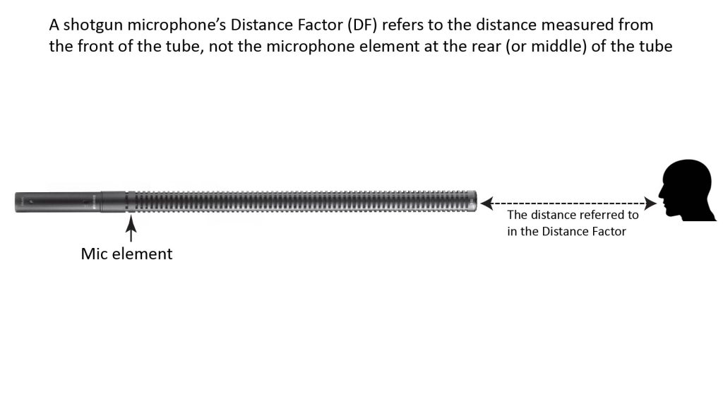
So, contrary to what you might read elsewhere, the length of a shotgun mic’s interference tube doesn’t count in its distance factor.
Why don’t shotgun microphones work well in a reverberant noise field?
You might have heard that shotgun mics don’t work well in reverberant noise fields, and if you’ve read most of this post so far, you should know why.
The reason is that the primary benefit of a shotgun microphone is relatively high directivity…and, as with all directional microphones, shotgun directivity varies inversely with wavelength (per equation 7 above). So shotgun microphone effectiveness is almost completely determined by the spectrum of the ambient noise.
If there is a lot of ambient noise power at frequencies below the shotgun mic’s critical frequency, then it won’t be any more effective at suppressing that noise than an ordinary hypercardioid microphone. And this is exactly the situation in a typical reverberant noise field: the noise spectrum is shifted lower in frequency than the direct sound, and other background noise in an indoor setting (such as from air conditioning) is also typically at a relatively low frequency.
So a shotgun microphone won’t work well in a reverberant noise field…but then, neither will any other type of similarly-sized directional microphone.
Is shotgun microphone self-noise important?
Because shotgun microphones are often used in areas with significant ambient noise, it might seem that their self-noise, also known as Equivalent Input Noise (EIN), isn’t as important as for studio microphones.
In fact, shotgun microphone EIN is important, because the directivity provided by a shotgun microphone reduces the ambient noise (especially at high frequencies) enough that self-noise is potentially audible.
For example, the following figure shows the predicted range of two shotgun microphones for 100-percent voice intelligibility in a typical indoor ambient noise field of 35 dBA: one is the Shure VP89L previously described (which has an EIN of 15 dBA), and the other is an identical microphone except with an EIN of 21 dBA:
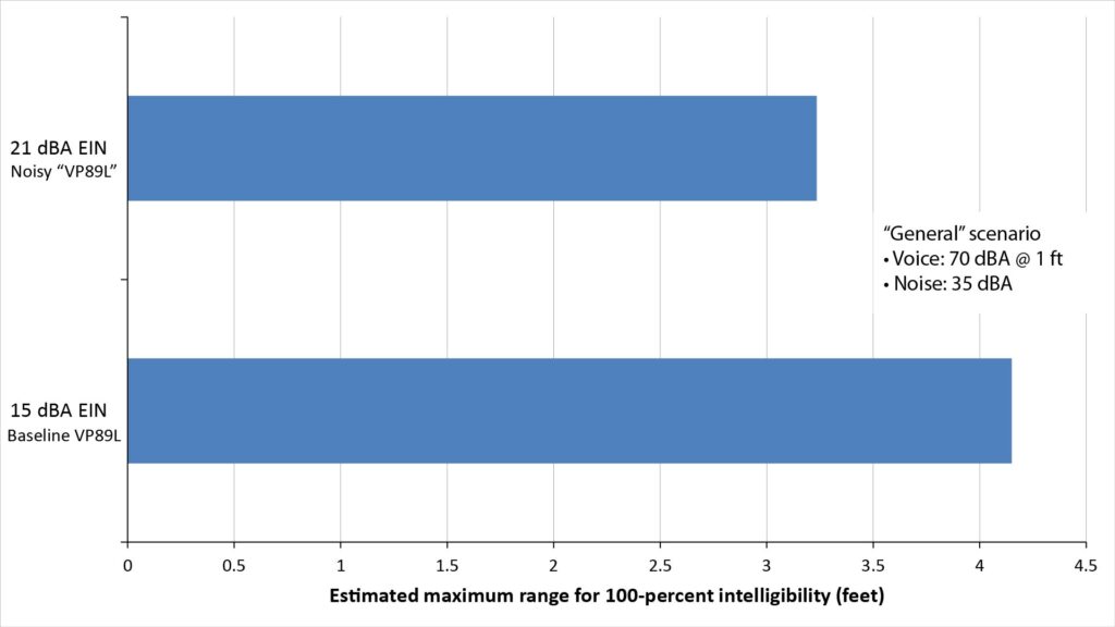
Note that the 6 dB greater EIN of the noisier microphone does, indeed, make a significant difference in the maximum range (or in the audible background noise level at a given range).
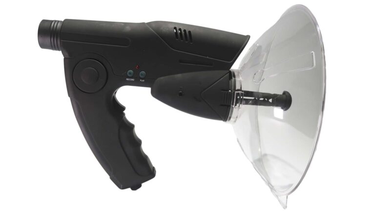
How do shotgun microphones compare to parabolic microphones?
Parabolic microphones aren’t generally thought of as potential alternatives to shotgun microphones because they’re usually much larger and capable of longer range. However, small parabolic microphones are indeed viable alternatives to shotgun microphones, as I show in The Klover MiK 09: can a small parabolic microphone outperform a shotgun microphone?.
How well do shotgun microphones really work?
Now that we know how shotgun microphones work, let’s discuss how well they work.
There are actually two parts to this question:
- Do real shotgun microphones live up to their performance claims?
- What’s the real-world benefit of the directionality provided by shotgun microphones?
Do real shotgun microphones live up to their performance claims?
A shotgun microphone’s signature capability is its ability to reject off-axis noise. So, we’ve already partially answered this question: we’ve shown that there is pretty good agreement between the polar patterns predicted by our simple Traveling Wave Model and the polar patterns Shure provides for the VP89L…and Shure is a pretty reputable manufacturer.
But even though we already know the answer, let’s take a closer look at the performance of real shotgun mics anyway.
First, let’s review the ways we can quantify a shotgun microphone’s ability to reject off-axis noise:
- The polar pattern plots the microphone’s signal power output (relative to the peak) as a function of the sound’s angle of arrival (per the example of Figure 8). An ideal shotgun microphone would have a narrow on-axis main lobe and a negligible off-axis output, regardless of frequency. Of course, the polar pattern of any actual shotgun microphone is frequency-dependent, as are the three other metrics described below.
- The beamwidth is the angular width of the microphone’s on-axis main lobe, at a specified frequency, over which the output is no less than some given fraction of the peak output. For example, the -3 dB beamwidth is the angular width over which the array factor is within 3 dB of the peak.
- As previously mentioned, the Directivity Index (DI) is the ratio of the on-axis sensitivity to the sensitivity averaged over all directions (thus, an omnidirectional microphone would have a DI of 0 dB).
- As previously mentioned, the Distance Factor (DF) is the increased range due to the DI in the presence of isotropic ambient noise. It represents the increase in range at which the additional inverse-square loss in SPL is compensated by the DI. For example, since a doubling of range results in an inverse-square loss of 6 dB, a microphone with a DI of 6 dB would have a DF of 2. Thus:
- DF = 10^(DI/20) (equation 8)
No single metric provides a complete picture of a shotgun microphone’s ability to reject off-axis noise, but if you had to pick one of the above, it would probably be the DF.
Actual shotgun microphone performance: the Sennheiser MD 82, Electro-Voice Model 642, and Shure VP89L
In order to assess the actual performance of shotgun microphones, I thought it would be interesting to compare two of the earliest shotgun mics on the market to the Shure VP89L we discussed above:
- The Sennheiser MD 82 was (at least according to Sennheiser) the first shotgun mic on the market, circa 1956. The MD 82 was also a very long shotgun mic, with an interference tube length of about 40 inches (corresponding to a critical frequency of about 170 Hz). One reason the MD 82 was so long is that it predated the invention of the combination cardioid/line microphone, and therefore had to rely purely on its interference tube for low-frequency directivity.
- The Electro-Voice Cardiline Model 642 (circa 1960) was the first combination cardioid/line microphone (based on the famous Beaverson/Ramsey U.S. patent 3,095,484). Because the Model 642 could rely on a cardioid element for low-frequency directivity, it could get away with a relatively short interference tube of just 12 inches (corresponding to a critical frequency of about 550 Hz).
- Finally, the Shure VP89L is a current model that is typical of today’s longer shotgun mics. Like all modern shotgun mics, it also uses a cardioid capsule and also has an interference tube length of about 12 inches (corresponding to a critical frequency of 550 Hz).
One of the reasons I chose the MD 82 and Model 642 is that, in 1962, BBC’s research department produced a very thorough report [3] documenting the results of testing they did on these two mics. The paper doesn’t discuss the Directivity Index (DI) or Distance Factor (DF), but does provide measured polar patterns (as well as frequency response curves).
I chose the VP89L for this discussion because its interference tube is almost exactly the same length as that of the Model 642. So, comparing it with the Model 642 might be interesting given the fact that 50 years separated the two microphones’ development.
-6 dB beamwidths
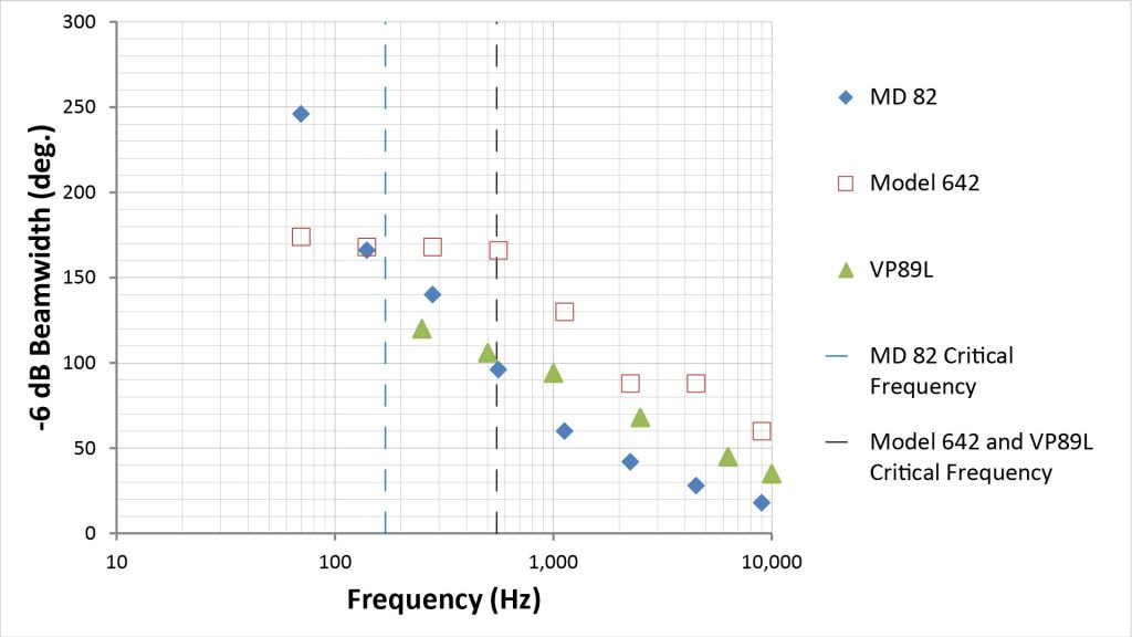
I decided to base my assessment on -6 dB beamwidths (because that’s what the BBC report provides). So I took the -6 dB beamwidths listed in Table 1 of the BBC report, along with eyeballed -6 dB beamwidths from the polar patterns given the VP89L user guide, to generate the beamwidth-versus-frequency plot of Figure 14:
Beamwidths above the critical frequency
Because of its longer interference tube, we would expect the MD 82 to have the narrowest beamwidths at the higher frequencies…and it does. In fact, its beamwidth at higher frequencies is about one-third that of the Model 642, which is what we would expect from an interference tube that’s three times as long.
However, there is a surprising discrepancy between the high-frequency beamwidths of the Model 642 and the VP89L. The interference tubes in these mics have the same length, so according to the simple model discussed previously they should have the same beamwidths. So why is the polar pattern of the VP89L so much sharper than that of the similarly-sized Model 642? Here are couple of hypotheses:
- The Model 642’s beamwidths were obtained through independent testing by the BBC, while the VP89L’s beamwidths were based on polar patterns supplied by the manufacturer. For marketing reasons, it’s possible that the latter might be more optimistic than the former…but I have no reason to suspect that that’s actually the case. I don’t own a VP89L, but after this analytical exercise, I’m thinking that I need to buy one and measure its polar pattern myself.
- As previously noted, more than 50 years separated the development of the two microphones. At the time the Model 642 was developed, it was known that manipulating the amplitudes of the sound components from each port in a line microphone (in addition to their phases) could increase directivity, but practical techniques for doing that were in their infancy. It’s possible that the VP89L uses some form of amplitude tapering (or some other directivity-enhancing technique) that was unknown in the 1960’s (and isn’t comprehended by our simple performance model). It would be surprising if 50 years’ of progress didn’t result in a significant increase in performance!
Beamwidths below the critical frequency
The low-frequency beamwidth of the MD 82 is exactly what we would expect of a pure line microphone with a pressure-type (not cardioid) element: it increases steadily with decreasing frequency down to 70 Hz (the lowest frequency at which the BBC made measurements), where it reaches 250 degrees. And it maintains the narrowest beamwidth of the three microphones down to about 300 Hz, which is what we would expect from its relatively long interference tube.
On the other hand, the Model 642’s low-frequency behavior shows clear evidence of a transition from a line microphone pattern to a cardioid pattern at 560 Hz, which is very close to the predicted critical frequency of 550 Hz (based on the Model 642’s tube length of 12 inches). And the -6 dB beamwidth below the critical frequency plateaus at 150 degrees, which is about what we would expect from a cardioid pattern.
Again, however, the VP89L’s behavior differs significantly from that of the similarly-sized Model 642. For one thing, there is no sign of a transition from a line-microphone pattern to some kind of cardioid pattern at the predicted critical frequency of 550 Hz. But that doesn’t mean there isn’t a transition; it just means that the transition is much more seamless, as would be expected from 50-plus years of progress. I suspect that the VP89L is designed to transition from the line-microphone response to some kind of cardioid response well above the critical frequency.
For another thing, the VP89L’s low-frequency beamwidth is much narrower than that of the Type 642. My hypothesis for this is that the VP89L uses a hypercardioid element, while the Type 642 uses a cardioid element. In fact, the VP89L’s -6 dB beamwidth at 250 Hz is 130 degrees, which is what we would expect of a hypercardioid capsule.
Conclusion: shotgun microphones do, in fact, live up to their performance claims
So what conclusions can we draw from this exercise? First, that all these shotgun mics are behaving pretty much as we’d expect them to behave.
And second, design attributes not comprehended in our simple Traveling Wave Model might, in fact, have a significant effect on performance, as evidenced by the Shure VP89L’s superiority over its noble ancestor, the Model 642. Of course, that apparent superiority is based on Shure-provided polar patterns, so any definitive conclusion is going to have to await some actual testing of VP89L on my part.
What’s the real-world benefit of the directionality provided by shotgun microphones?
So shotgun mics are actually as directional as they’re supposed to be. But what’s the real-world benefit of that directionality?
Probably the most meaningful metric to gauge a shotgun microphone’s real-world effectiveness is the maximum range at which it can pick-up sound of a given quality.
Real-world maximum range
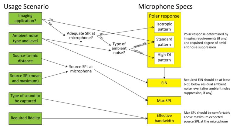
As with any directional microphone, the maximum range of a shotgun microphone depends on three factors:
- the required signal-to-noise ratio as a function of frequency,
- the sound-pressure level and spectrum of the sound to be captured, and
- the sound-pressure level and spectrum of the ambient noise.
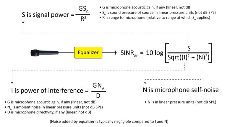
Weighing these factors to estimate microphone range involves evaluating the Signal-to-Interference-plus-Noise Ratio (SINR) at the microphone output as a function of frequency. That’s not a trivial endeavor; in fact, I have a whole series of posts on it:
- Predicting microphone performance—Part 1: what is microphone SINR?
- Predicting microphone performance—Part 2: using the SINR
- Predicting microphone performance—Part 3: microphone range prediction
So, in the remainder of this post, I’m going to just present some range projections without explaining how they were obtained; refer to the aforementioned series of posts if you want the gory details.
All of the projections given below were for what I call the “General” microphone usage scenario, which involves picking-up human voice with a broadband SPL of 70 dBA at 1 foot from the source, in the presence of a broadband ambient noise level of 35 dBA (biased toward low frequencies, as is typical of indoor environments). These assumptions are typical of what might be expected in a videography application in a reasonably quiet room.
The following figure shows the predicted maximum range of both the VP89L (which has a 12-inch interference tube) and a hypothetical 20-inch version of VP89L, compared to that of isotropic and hypercardioid microphones—all with the same EIN of 15 dBA:
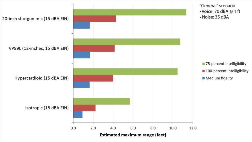
This ranges shown in this figure might surprise you. The shotgun microphones do, indeed, have longer pick-up ranges than do studio microphones in this scenario, but not by much. In fact, the range of even a 20-inch shotgun microphone isn’t noticeably greater than that of a hypercardioid studio microphone.
The reason is that the frequency-dependent directivity of a shotgun microphone exceeds that of a hypercardioid only above 2 kHz (for the VP89L) or 1 kHz (for the 20-inch shotgun), while the ambient noise in typical indoor environments rolls-off at about 5 dB per octave with increasing frequency.
So, while the greater directivity of a shotgun microphone does provide a significant reduction in the ambient noise at high frequencies, it has a relatively small effect on the sound quality.
The upshot of all this is that the real-world benefit of practically-sized shotgun microphones is real but modest. You’d need an interference tube of at least 3 or 4 feet to realize a dramatic improvement over a hypercardioid studio microphone.
References
- Shure VP89 User Guide, https://pubs.shure.com/guide/VP89/en-US. Accessed December 2021.
- Bai, Mingsian & Lo, Yi-Yang. (2013). Refined acoustic modeling and analysis of shotgun microphones. The Journal of the Acoustical Society of America. 133. 2036-45. 10.1121/1.4792147. Available at https://www.researchgate.net/publication/236111928_Refined_acoustic_modeling_and_analysis_of_shotgun_microphones [accessed June 2021].
- W. I. Manson, “The Sennheiser Type MD 82 and ElectroVoice Type 642 Microphones”, BBC Research Department Report L-052, 1962. Available at https://rdweb1.lh.bbc.co.uk/rd/publications/rdreport_1962_41 [accessed June 2021].