The post provides an overview of Electret Condenser Microphones (ECMs) and describes practical ways of using them to drive standard microphone inputs.
What are Electret Condenser Microphones?
Condenser is an archaic term for capacitor. A condenser microphone is actually a parallel-plate capacitor, except that one of the plates is a flexible conductive diaphragm that is allowed to vibrate with incoming sound waves.
When there is a constant electric field between the plates of a capacitor, the voltage across the plates will vary with the distance between them. So, the vibrating diaphragm in a condenser microphone creates a voltage that represents the incoming sound waves.
One way to generate the necessary electric field is to apply a DC voltage across the plates through a resistor; the AC voltage generated by the vibrating diaphragm can then be tapped-off with a DC-blocking capacitor. That’s called external polarization, and is how studio condenser microphones work.
But just as a magnetic field doesn’t always require an external current, an electric field doesn’t always require an external polarizing voltage. Indeed, there’s an electrostatic equivalent of the permanent magnet: it’s called an electret, and it consists of a dielectric material that has a virtually permanent electrostatic charge.
Electrets have been around since the early 1700’s. However, initial attempts to make a workable electret condenser microphone didn’t have much success because the electric field strength produced by an electret is much weaker than the field strength achievable with an external polarizing voltage. The breakthrough came in the early 1960’s when James West at Bell Telephone Laboratories got the idea to put an electret between a pair of taut, tiny, metalized Mylar films, with one film allowed to vibrate with incoming sound. This configuration enabled a relatively small spacing between the films, producing a usable signal with the relatively low field strength provided by the electret.
However, that early electret microphone (like all condenser microphones) had an output impedance far too high to be directly connected to a standard microphone input. So, the final step in the development of the modern electret microphone element was to integrate a tiny Field-Effect Transistor (FET)—which has a virtually infinite gate impedance—into the same package as the metalized films.
Thus, the modern Electret Condenser Microphone (ECM) element is a tiny package in which an electret is placed between a pair of metalized films, and which integrates a FET to buffer the signal output.
Why you should use an ECM element for your DIY microphone
A detailed comparison between the various types of microphone elements is beyond the scope of this post. However, suffice it to say that ECM elements offer a combination of cost-effectiveness, versatility, small size, and ease-of-use that can’t be matched by any other type of microphone. Of course, some ECM elements are better than others, as discussed in my post on The 7 best microphone elements for cost-effective DIY microphones.
The main limitation of ECM elements is their inability to handle very high Sound-Pressure Levels (SPLs) without distortion. This limitation is partially due to non-linearity in the FET buffer, and partly due to the ECM’s relatively small size.
So, if you need to handle extremely high SPLs—such as to close-mic an opera singer—then you’ll be better off with a dynamic or externally-polarized (large-diameter) condenser microphone, rather than an ECM. However, for the vast majority of applications, an ECM will provide more than enough distortion-free SPL capacity…and they’re far, far less expensive and easier to use. I discuss maximum SPL requirements for microphones (along with other key specs) in detail in The 4 key microphone specifications.
Micro-Electro-Mechanical System (MEMS) microphones, used widely in smartphones and voice-assistants, are also of interest to the DIY microphone builder. Like ECM elements, MEMS microphones consist of a microphone element (which is often an electret-condenser element) integrated with active circuitry. However, a MEMS microphone can also use other types of elements (such as piezoelectric elements), and the active circuitry in a MEMS microphone is more elaborate than the bare FET buffer in an ECM element. Some Micro-Electro-Mechanical System (MEMS) microphones can equal the performance of high-quality ECM elements, but they don’t offer any cost advantage and are slightly more difficult to use due to the need for surface-mount soldering. MEMS microphones are better for certain DIY applications (e.g. array microphones), but for general-purpose DIY use, you can’t beat a high-quality ECM element.
Two-terminal versus three-terminal ECM elements
The vast majority of ECM elements available today have two terminals, but a few have three. The difference has to do with how the FET buffer that’s integral to all ECM elements is intended to be used.
The FET buffer in a two-terminal ECM is intended to be used in a common-source configuration, whereas the buffer in a three-terminal ECM is intended to be used in a common-drain configuration:
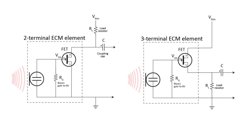
The three-terminal common-drain configuration allows somewhat greater SPLs to be handled without distortion and reduces output impedance, but also reduces sensitivity. However, the ECM market seems to have standardized on the two-terminal configuration, which offers more than enough distortion-free SPL—and a low enough output impedance—for most applications. For this reason, the rest of this post will address only the two-terminal configuration.
The basic ECM operating circuit
To actually operate as a usable microphone, an ECM element needs a bias voltage, a load resistance, and an output coupling capacitance:
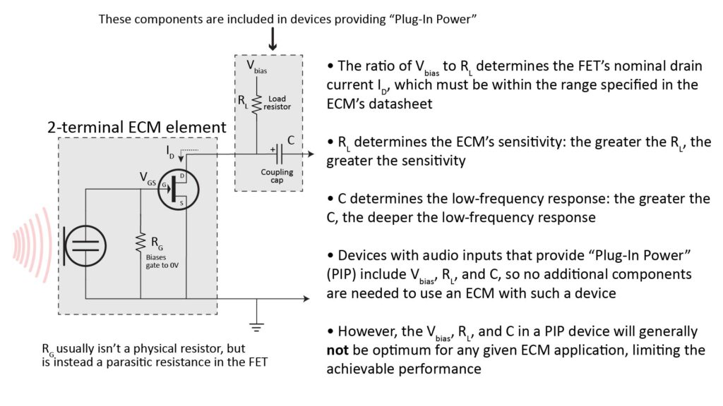
The bias voltage Vbias powers the FET buffer, the load resistor RL limits the DC current through the FET and converts the AC current variation caused by the incoming sound into a varying drain voltage, and the coupling capacitor C passes only the AC component of the drain voltage to the downstream audio input.
How the bias voltage and load resistance affect ECM performance
To provide the greatest linearity and dynamic range, the average drain current ID of the FET buffer in an ECM should be kept within a narrow range. For a given ECM, the average drain current will depend on the bias voltage Vbias and load resistance RL; the greater the Vbias, the greater the required RL to maintain a desired ID.
In addition to establishing the nominal drain current for a given Vbias, RL also determines the gain of the buffer. The value of RL is a tradeoff:
- The lower the value of RL (which also requires a commensurate reduction in Vbias), the lower the sensitivity of the ECM.
- The higher the value of RL (which also requires a commensurate increase in Vbias), the greater the usable sensitivity of the ECM—but only as long as RL is significantly smaller than the input impedance of the downstream device (which might be something like 10K). Further, the higher the value of RL, the greater the sensitivity of ID to variations in temperature and FET characteristics, potentially creating a risk that the average ID will drift outside the desired range.
The datasheets for most ECMs specify a recommended average ID, as well as a suggested Vbias and RL. Conveniently, the specified Vbias is usually typical of the supply rail voltage in modern electronic devices, such as 3.3V or 5V.
The usual design procedure for a device using an ECM is to use whatever voltage is handy for Vbias (which will be typically be close to the datasheet-specified value) and to then select a value of RL that yields an average ID close to the datasheet-specified value.
However, there is a very good reason why you might want to stray far from the datasheet-recommended values; I’ll discuss that in more detail later in this post.
By the way, Why you shouldn’t rely on microphone plug-in power has a more in-depth discussion of the topic of varying the ECM load resistance.
Coupling capacitance determines low-frequency response
In Figure 2, the purpose of the coupling capacitor C is to block the DC bias voltage for the FET, passing only the AC component (i.e. the signal) to the output. Thus, the capacitor acts as a first-order high-pass filter with a -3dB corner frequency equal to 1/(2
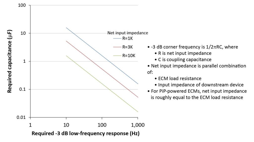
Since the impedance of the downstream device isn’t always known, a good rule-of-thumb is to pick a value of C that yields the desired -3dB low-frequency cutoff (say, 20 Hz) for an AC impedance equal to half the load resistance RL. RL will typically be no less than 2K, so a value of 8 uF (rounded up to 10 uF) will ensure that the -3dB cutoff is no greater than 20 Hz.
Using an ECM element with a device that provides Plug-in Power
Since their inception in the early 1960’s, ECMs have become so widely used that many consumer devices with microphone inputs already supply the bias voltage, load resistance, and coupling capacitance needed by an ECM (see Figure 2 above). Devices that do this are said to supply Plug-in Power (PiP).
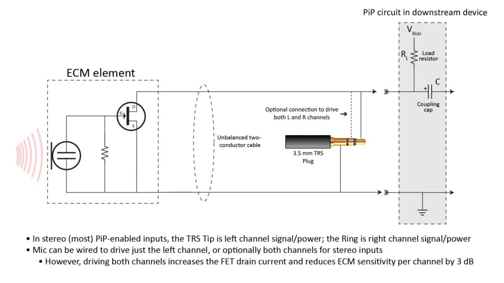
In fact, most devices with 3.5mm Tip-Ring-Sleeve (TRS) microphone input jacks supply Plug-in Power (PiP). These include include desktop and laptop computers, some tablets and smartphones, many field recorders, and many cameras.
If you want to use a bare ECM element with such a PiP-enabled device, you don’t necessarily need do anything more than to wire it up with a cable and connector.
There are a couple of different PiP wiring schemes, and exactly how you wire-up the ECM element to the plug depends on which scheme your device uses; see my post on microphone back-end design for more details. However, this is the most common configuration:
However, there are other (and better) ways to use an ECM element with a device that provides PiP.
Disadvantages of PiP
PiP is obviously an extremely convenient way to power an ECM-based microphone, and under the right conditions a PiP-powered microphone can provide excellent performance. However, PiP does have some potentially serious disadvantages, as discussed in detail in Why you shouldn’t rely on microphone plug-in power. However, here’s a brief summary:
PiP bias voltage and load resistance are not necessary optimum
As described previously, every ECM has a FET buffer, and every FET buffer has a certain optimum drain current at which the linearity and dynamic range are maximized. This optimum drain current can vary significantly from ECM to ECM. Further, there is no firm standard for the bias voltage and load resistance provided by a PiP-enabled device.
Thus, there is a good chance that the bias voltage and load resistance provided by a particular PiP-enabled device won’t be optimum for a given ECM. This can significantly degrade the ECM’s performance (e.g. via reduced sensitivity and dynamic range, or via increased Total Harmonic Distortion, aka THD).
To avoid this, it’s a good idea to either measure the PiP bias voltage and load resistance (which is very easy to do, as described in my post on PiP), or measure the actual drain current when powering the ECM in question. If the ratio of the PiP bias voltage to load resistance is very different from the ratio of bias voltage to load resistance specified in the ECM’s datasheet—or if the measured drain current differs significantly from the datasheet-specified value—then it’s best not to rely on PiP for that particular ECM.
Fortunately, there are several ways to use an ECM without PiP, as I’ll describe later in this post.
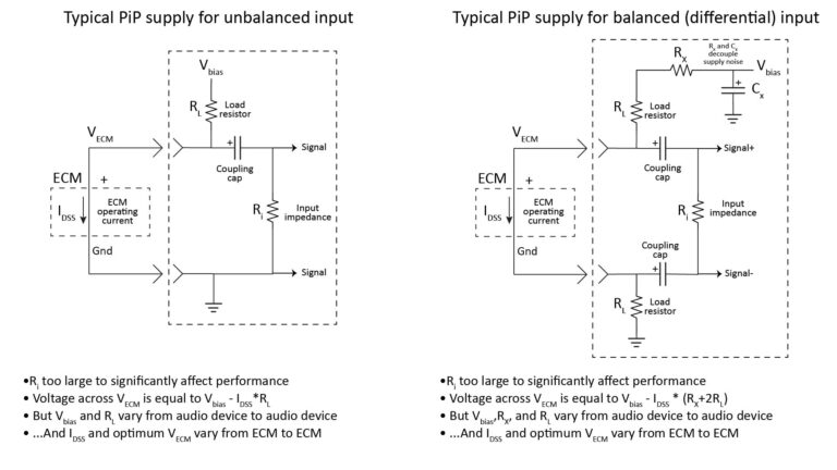
PiP inputs are unbalanced
The second disadvantage of PiP is that it uses just two connections to the microphone: signal/power and ground.
This is referred to as an unbalanced input, because each connection has a different impedance with respect to ground (the ground connection obviously has a zero impedance with respect to ground, while the signal/power connection has a non-zero impedance with respect to ground).
Unbalanced inputs are susceptible to common-mode noise
With an unbalanced input, any electromagnetic interference picked-up on the ground connection will be shorted to ground, but the same interference picked-up on the signal connection will add noise to the desired signal.
This so-called common-mode noise can be (and generally is) minimized by using a shielded cable between the microphone and PiP device. With a shielded cable, common-mode noise typically isn’t a problem when the cable is less than a few feet long and used in an electrically quiet environment. Otherwise, it can definitely be audible.
This is why microphone inputs on prosumer devices use a balanced connection. A balanced connection has three wires (two signal wires and a ground), with each signal wire having exactly the same impedance with respect to ground (hence the term “balanced”).
To take full advantage of a balanced connection, the microphone must provide a differential output, wherein the incoming sound pressure is represented as the difference in the voltages of the two signal wires with respect to ground. Similarly, the downstream device must have a differential input stage that subtracts the voltages on the signal wires to recover the desired signal.
The advantage of this configuration is that the common-mode component of any noise picked-up on the signal wires gets subtracted-out in the differential input stage. With the right choice of cable, almost all of the electromagnetic interference picked up on the cable will be common-mode noise, so the balanced configuration can dramatically reduce the noise level (especially with long cables).
Fortunately, an ECM can indeed be used to produce a differential signal that can drive a balanced input stage, as I’ll describe later in this post.
PiP can supply only a limited amount of power
The final disadvantage of PiP is that the load resistor is sized to provide only enough current for the ECM—and nothing else.. This is fine for microphones that don’t include any active circuitry in addition to the ECM element (like active filters or summing amplifiers). Most DIY microphones fall into this category.
However, some advanced microphones do need more power than can be supplied by PiP. Fortunately, there are plenty of ways to power such microphones without relying on Pi2P.
Using an ECM element without Plug-in Power
There are many circumstances in which you might want to use an ECM element without PiP, but the most common scenarios are as follows:
- You want to use your DIY microphone with a device that supplies PiP, but you don’t want to rely on the device’s choice of bias voltage and load resistance.
- You want to use your DIY microphone with a prosumer-caliber device that has balanced inputs which provide Phantom Power.
- You want to use your DIY microphone with a device that either doesn’t provide any microphone power or doesn’t provide enough microphone power (e.g. because the microphone includes a preamplifier or active filter).
We’ll consider each of these separately.
Using an ECM with a PiP-enabled device without relying on the PiP supply
As previously mentioned (and described in more detail in my post on PiP), a given PiP-enabled device might not have the appropriate bias voltage and load resistance to obtain the best performance with a given ECM element.
Fortunately, you can easily get around this problem by supplying your own bias voltage, load resistance, and DC-blocking coupling capacitor:
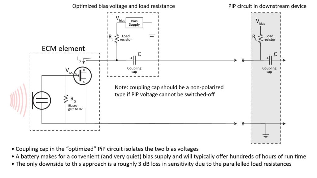
As previously described, the bias voltage and load resistance should be chosen to yield the datasheet-specified value of average drain current for the ECM in question, and the coupling capacitance should be chosen to provide the desired low-frequency response.
However, when figuring the required capacitance, note that your DC-blocking capacitor is in series with the PIP supply’s coupling capacitor, and that the AC impedance at the FET drain is equal to the parallel combination of your load resistor and the PiP supply’s load resistor:
- Because the coupling capacitances are in series, the coupling capacitor will have to bigger than you’d otherwise expect (perhaps by a factor of two) to get the desired low-frequency response. The capacitor’s required voltage rating is actually reduced due to the series connection, but it’s best to err on the side of caution and choose a capacitor with a voltage rating of about twice the maximum expected PiP bias voltage; a rating of 10V will generally be sufficient.
- The figure shows a polarized capacitor with the positive terminal facing the ECM element. This assumes that the audio device allows the PiP voltage to be turned-off. If that’s not the case, then a non-polarized capacitor must be used. This usually isn’t a big deal since the capacitor doesn’t need voltage rating greater than about 10V.
- Because the load resistances are in parallel, the sensitivity of the ECM will be reduced by approximately 3 dB. However, this is generally a non-issue with high-quality ECMs which have a relatively low self-noise.
Sourcing the bias voltage
A battery is the simplest way to supply the bias voltage in the configuration of Figure 5…and the only one that doesn’t add any noise to the signal chain. Of course, a battery also has the disadvantage of needing to be replaced or recharged periodically. However, that’s not much of a disadvantage because the battery lifetime can be quite long.
For example, I typically use an AA-sized, non-rechargeable lithium thionyl chloride (Li-SOCl2) battery to power ECM-based microphones. An Li-SOCl2 battery has some pretty significant advantages in this application:
- A single Li-SOCl2 cell has a nominal voltage of 3.6V, which is about right to power an ECM assuming an appropriate choice of load resistance.
- An AA-sized Li-SOCl2 cell has a capacity of 2700 milli-amp-hours (mAH) and a shelf life of over 10 years. Since a typical ECM draws less than 1 mA, a single AA Li-SOCl2 battery will provide more than 2,700 hours of operating time—so you might never need to replace it.
- Unlike some other battery types (notably alkaline), an Li-SOCl2 cell maintains a nearly constant output voltage over its lifetime.
For these reasons, a single AA-sized Li-SOCl2 battery is an excellent way to power an ECM-based microphone.
But if you don’t want to use a battery, there are at least two other options to source the bias voltage (other than PiP or, as we’ll discuss later, Phantom Power):
- USB power (+5V) is convenient but often electrically noisy. Fortunately, USB power can be cleaned-up fairly easily with an RC filter.
- A regulated mains-powered supply (such as a wall-wart or power-brick). Also potentially noisy but also amenable to noise suppression via RC filtering.
Using an ECM with a balanced input that provides Phantom Power (PP)
Microphone inputs on higher-quality audio devices don’t provide PiP; instead, they are fully balanced and virtually always capable of providing Phantom Power (PP). Even some inexpensive devices (such as budget USB audio interfaces) have PP-capable balanced inputs. And most modern devices that provide PP also allow the power to be turned-off via either a physical switch or a menu setting.
So, if you’re a DIY microphone builder, approaches for using ECM-based microphones with PP-enabled devices are likely to be of great interest. Before reviewing those approaches, let’s take a quick look at how Phantom Power and balanced inputs work.
How balanced inputs and Phantom Power work
The following figure shows a balanced input stage with Phantom Power (PP):
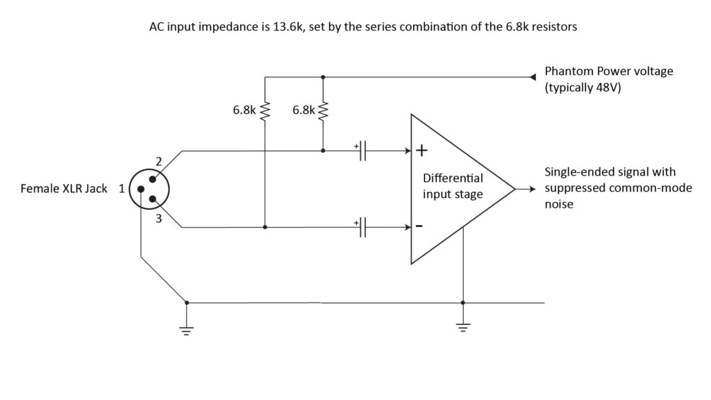
Like Plug-in Power (PiP), Phantom Power (PP) is based on the fact that DC power can be carried on the same wire as an audio (AC) signal by using capacitors to isolate the DC from the AC. But, while a PiP-enabled input has a single signal terminal and a single capacitor, a PP-enabled input has two signal terminals and two capacitors, and it uses a much higher voltage (typically 48V), which is provided via 6.8K resistors. Each signal line has exactly the same voltage with respect to ground—and thus there are exactly zero volts between the two signal lines.
So, a microphone which needs external power (like one using an ECM or an externally-polarized condenser capsule) can draw power from the signal lines (using the ground connection as the return path). But a microphone which doesn’t need power (like a dynamic or crystal type) can be connected between the signal lines without damage (omitting the ground connection), since the signal lines are at exactly the same DC voltage.
The “balanced” aspect of this configuration refers to the fact that each input has exactly the same impedance, and that the inputs are connected (via the DC-blocking capacitors) to a differential input stage which subtracts the two signals.
To take full advantage of this configuration, the microphone should also have a balanced output, producing a differential signal with exactly the same impedance on each output line. However, as I’ll describe below, that doesn’t necessarily have to be the case.
For now, assume that the microphone does have a balanced output. Then, because each signal line has the same impedance with respect to ground, any electrical interference picked up on the cable between the microphone and the PP input will be exactly the same on both input lines, and will therefore be subtracted-out by the differential input stage:
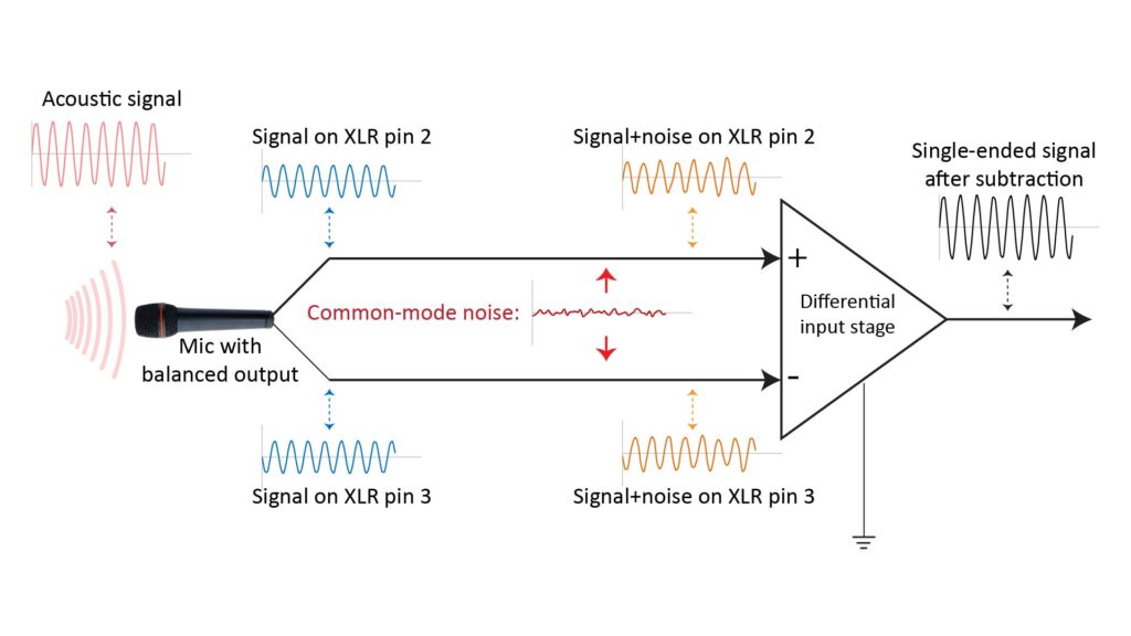
In the figure above, the microphone is listening to a steady tone. Therefore, it produces two pure sine waves, 180 degrees out-of-phase, on each of its two balanced outputs. If the cable is fairly long and in an electrically noisy environment, each signal will get corrupted by noise by the time it reaches the differential input stage.
And that’s where the magic of balanced inputs happens: any noise in common across the two signals (the so-called “common-mode noise”) gets subtracted out. On the other hand, because the desired signals are 180 degrees out-of-phase, subtracting them doubles the amplitude, increasing the signal amplitude by 3 dB and the signal power by 6 dB.
However, if the signal lines don’t have exactly the same impedance with respect to ground, then any electrical noise picked up on the cable won’t be fully subtracted-out in the differential input stage. And if the microphone doesn’t have a differential output, the differential input stage won’t provide the expected 6 dB increase in signal power.
Using an ECM with Phantom Power via an unbalanced connection
Often, the best reason for wanting to use an ECM-based microphone with a PP-enabled input is not to gain the benefits of a balanced connection, but rather because the audio device in question doesn’t have PiP-enabled inputs. In fact, the acoustic noise picked up by a microphone is often much greater than the electrical noise picked up on the cable, in which case a balanced connection would provide no audible benefit in signal quality.
In such a situation, an unbalanced connection might be preferred because an ECM-based microphone with an unbalanced output is easier to build than one with a balanced output. So, let’s examine several approaches fur using an ECM in a unbalanced configuration to drive a PP-enabled balanced input.
Using the basic ECM circuit with a separate bias supply
An ECM-based microphone that has its own bias supply (such as the one shown previously in Figure 5 for use with a PiP-enabled input) can also drive a balanced input that provides PP.
If you wire such a microphone with a 3.5mm TRS plug as shown in Figure 4, then you can use it not just with a PiP-enabled input (via the 3.5 mm plug), but also with a PP-enabled input (via an off-the-shelf TRS-to-XLR adapter). Since the microphone has its own bias supply, the TRS-to-XLR adapter can be of the relatively inexpensive type that doesn’t need to convert PP power to PiP power, such as the Rode VXLR (about $10). Notably, the much more expensive VXLR Plus (which includes a PP to PiP voltage converter) or the VXLR Pro (which provides a fully balanced connection) are unnecessary with this unbalanced battery-powered ECM configuration.
However, there are a couple of provisos with this approach:
- As previously mentioned, most PP-enabled audio devices provide the option to turn off the PP voltage. If that’s the case, and if you are sure that the PP voltage will be switched-off before you plug-in the microphone, then you can use the circuit of Figure 5 unchanged: the capacitor voltage rating can be about twice that of your bias voltage (such as 10V for a 5V bias voltage), and if a polarized cap is used, its positive terminal should be oriented as shown.
- On the other hand, if your intended PP-enabled device doesn’t offer the option to switch off the power (or you think you might forget to turn it off before you plug in the microphone), then the coupling capacitor in the Figure 5 circuit must have a voltage rating high enough to withstand the PP voltage. For standard 48V PP, a rating of around 60V should be sufficient, and the capacitor polarity should be flipped so that the positive terminal faces the PP input.
Powering an ECM via Phantom Power through a Zener diode via an off-the-shelf adapter
The aforementioned Rode VXLR Plus TRS-to-XLR adapter (about $25) uses a Zener diode to drop the PP voltage down to about 5V (which is more typical of PiP), and also subsumes the load resistor and coupling capacitor found in a PiP-enabled input. So, it effectively turns an PP-enabled microphone input into a PiP-enabled microphone input. Similar adapters are available at lower cost from other manufacturers.
Zach Poff has a great post on such adapters, showing a typical schematic and describing his test results for different units. Based on his observations and my own experience, the Rode VXLR Plus is a well-designed product—but I would recommend against buying such an adapter that isn’t made by Rode.
Also, even the Rode VXLR Plus has a significant issue: because it converts a microphone input that provides PP into one that provides PiP, it has the same performance limitations as all PiP inputs. Specifically, the bias voltage and load resistance are fixed and might not be optimum for whatever ECM you’re using. I discuss PiP limitations in detail in this post.
Isn’t Zener diode noise another disadvantage of such adapters?
Notice that my assessment of commercial PP to PiP adapters above didn’t mention Zener diode noise as an issue. You might have heard that Zener diodes are noisy, and it’s true that all Zener diodes operated as voltage regulators generate some noise. However, the noise isn’t necessarily high enough to be an issue, and it isn’t necessarily greater than the noise produced by other types of voltage regulators. Further, the noise can be essentially eliminated via a simple RC filter (as in the case of the Rode VXLR Plus).
One of the most informative references on the subject of Zener noise is the data posted by Christer at DIYaudio.com, circa 2004, in this thread. Christer’s data shows that Zener diodes with a breakdown voltage of around 5 to 6 volts are indeed relatively noisy, but that those with significantly lower or higher breakdown voltages can be surprisingly quiet. This is assumed to have something to do with the fact that 5 to 6 volts is the transition point between the Zener effect (which dominates at low voltages) and the avalanche effect (which dominates at higher voltages).
For example, Christer’s data shows that a 12V Zener operating at 1 mA can have a noise of the order of just 0.3 uV RMS across the audio bandwidth, which is quiet enough to be a non-issue. RC noise filtering would be unnecessary with such a quiet diode. However, including RC noise filtering doesn’t hurt, and eliminates noise as a consideration in choosing the diode voltage.
Wouldn’t a low-noise voltage regulator be quieter than a Zener diode?
A low-noise voltage regulator is certainly a viable alternative to a Zener diode. But few small low-noise regulators can directly handle the 48V phantom power voltage, so a Zener is generally needed anyway to first drop the voltage to a manageable level. Further, as Christer’s results show, a low-noise regulator won’t necessarily be quieter than a Zener diode.
So, the only real advantage of a low-noise regulator would be greater current capacity (e.g. to power an active filter or output buffer)—and that’s moot because the current will be limited by the 6.8K resistors in the PP supply anyway.
DIY equivalents to commercial adapters
The most common DIY way of powering an ECM from PP is to copy the commercial adapters’ approach of using a Zener diode to drop the 48V to a manageable value. The main benefit of the DIY approach (besides being less expensive) is that the load resistance can be optimized for whatever ECM part number you’re using, and the Zener voltage can be chosen to minimize noise.
However, I personally don’t use this approach, for three reasons:
- I use the Rode VXLR Plus for ECM elements that I know are reasonably well-matched to the VXLR’s Zener voltage and load resistance. I’ll cover that in more detail in another post.
- Otherwise, I prefer the increased load resistance approach described below for most of my high-performance microphones, because it’s simpler, less expensive, and works just as well.
- When the increased load resistance approach isn’t appropriate (e.g. when I need to drive long cables, or when the microphone includes active circuitry which requires more power than can be supplied by PP), I supply my own bias voltage (typically using a battery), as in Figure 5.
So, I’m not going to describe DIY PP-to-PiP adapters further in this post. If you’re interested in building one, drop me a line; if there’s enough interest I’ll write a detailed post on the subject.
The increased load resistance approach
If your microphone contains no active circuitry other than an ECM element, then a simple solution to power it via PP is to just use the standard ECM circuit of Figure 2—but with a much larger value of load resistance and a higher capacitor voltage rating. This works because the FET buffer inside the ECM cares only about drain current; if the load resistance is increased to provide the specified drain current with 48V, the ECM element will operate nominally from 48V PP.
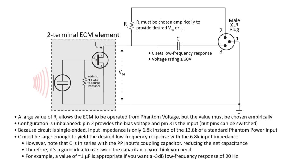
Note that Figure 8 shows XLR pin 2 supplying the bias voltage and XLR pin 3 accepting the input. However, because this is a single-ended (not differential) configuration, the pins could be interchanged so that pin 3 supplies the bias voltage and pin 2 accepts the input. The only difference would be a 180-degree phase-change in the output signal. For this reason, if you’re building multiple microphones that use this approach, it’s a good idea to stick with the same XLR pin (either 2 or 3) to carry the signal so that the outputs will be in-phase if you decide to do multi-channel recording. An exception to this would be if you want a 180-degree phase shift between the microphones (e.g. for specialized beamforming or imaging applications)—but that’s a topic for another post.
The use of a higher-valued load resistor to bias an ECM via Phantom Power is a well-known hack. Tom Benedict has a great post on implementing such a two-component PiP circuit inside an XLR connector which can be plugged-in to any device that supplies PP.
There are a few things to note about this approach:
- The required load resistance will be larger by roughly the ratio of voltages. So, an ECM specified for a 2.2K load resistance with a bias of 5V would require a load resistance of roughly 21K. However, the load resistance should be determined empirically for each individual ECM element, and not via calculation from the datasheet—and ideally at the maximum expected operating temperature. This is because increasing the load resistance also increases the circuit’s sensitivity to part-to-part and temperature-induced variations in the nominal drain current of the ECM’s FET buffer. So, a high load resistance optimized for one ECM of a given part number could be unworkable with another ECM of the same part number. When optimizing the load resistance, start out with a high-valued resistor and work your way down (otherwise, the voltage across the ECM could easily be high enough to damage it) until the measured drain current or drain-to-source voltage reaches the nominal value specified in the datasheet. See my post on why you should avoid PiP power for more information on how ECM JFET buffers work and the effects of varying the load resistance.
- Obviously, a particular value of load resistance will work only with a particular PP voltage. This isn’t much of an issue, though, because virtually all PP-enabled devices provide 48V (although some offer the option of other voltages). So choosing the resistance based on 48V will ensure broad interoperability.
- If it weren’t for the input impedance of the downstream PP input, the relatively high load resistance would greatly increase the signal amplitude (or, equivalently, the ECM’s sensitivity), generate more thermal (Johnson) noise, and interact with the cable capacitance to reduce the high-frequency response. However, the resistive component of the AC impedance seen by the ECM is actually the parallel combination of the ECM load resistance and the impedance of the downstream PP input (i.e. the series resistance of the two 6.8k resistors, or 13.6k). Therefore, no matter how large the load resistance, the ECM signal will see no more than 13.6k, which is about a factor of four times higher than that of the load resistance in a “regular” ECM circuit. This is significant but not huge, so any increase in sensitivity will be modest, and the increase in noise will typically be inaudible. The same is true for the reduction in high-frequency response, assuming that a reasonably low-capacitance cable (e.g. less than 400 pf per meter) is used; almost any microphone cable (such as the any of the bulk microphone cables offered by Mogami) will meet this requirement.
- The coupling capacitor must obviously withstand the Phantom Power voltage; a voltage rating of ~60V should suffice for 48V PP. Further, the capacitance must be large enough to provide the required low-frequency response when driving the 6.8k single-ended input impedance of the Phantom Power input. However, note that the effective coupling capacitance isn’t just the value of the coupling capacitor shown in Figure 8; it’s actually the capacitance of the series combination of C and the coupling capacitor inside the PP circuit. A good rule-of-thumb is to double the value capacitance calculated from the 1/2
π fR equation (where f is the desired low-frequency response and R is 6.8k), e.g. a value of about 1μ F should be chosen for a -3dB response down to 40 Hz.
Because there is no suppression of common-mode noise with this unbalanced circuit, it makes little difference if the resistor and capacitor are located on the microphone side of the cable or at the device side of the cable. That’s why Tom Benedict’s approach of integrating the components inside the XLR plug makes sense, because it minimizes the size of the microphone assembly (e.g. for lavalier applications).
Using an ECM with Phantom Power via a balanced connection
While the unbalanced configurations described above are the easiest ways to use an ECM with a PP-enabled input, it’s actually not much harder to implement a balanced connection between the microphone and the PP input. Again, there are several ways to do this; let’s look at a few of them.
Using an off-the-shelf adapter with balanced output
In addition to the aforementioned VXLR (which doesn’t provide power) and the VXLR Plus (which provides PiP-like power with an unbalanced output), Rode also makes the VXLR Pro, which includes an audio transformer to provide a balanced output.
To get the benefit of the common-mode noise suppression provided by the VXLR Pro, the unbalanced cable between the mic and the adapter must be as short as possible.
Also, the VXLR Pro costs $40, which is a lot to spend for an adapter, and it still has the disadvantage of a fixed bias voltage and load resistance which might not necessarily be optimum for the ECM you’re using.
Still, it’s a great solution if the bias voltage and load resistance are a good match for your ECM. I’ll link to a post on that subject here.
Using a separate bias supply with a split load resistance
In the standard ECM circuit of Figure 2 (as used in all devices that supply PiP), the load resistance is in the form of a single resistor connected between the bias voltage and the FET drain.
Alternatively, the load resistance can instead be split between a drain resistor and a source resistor, like this:
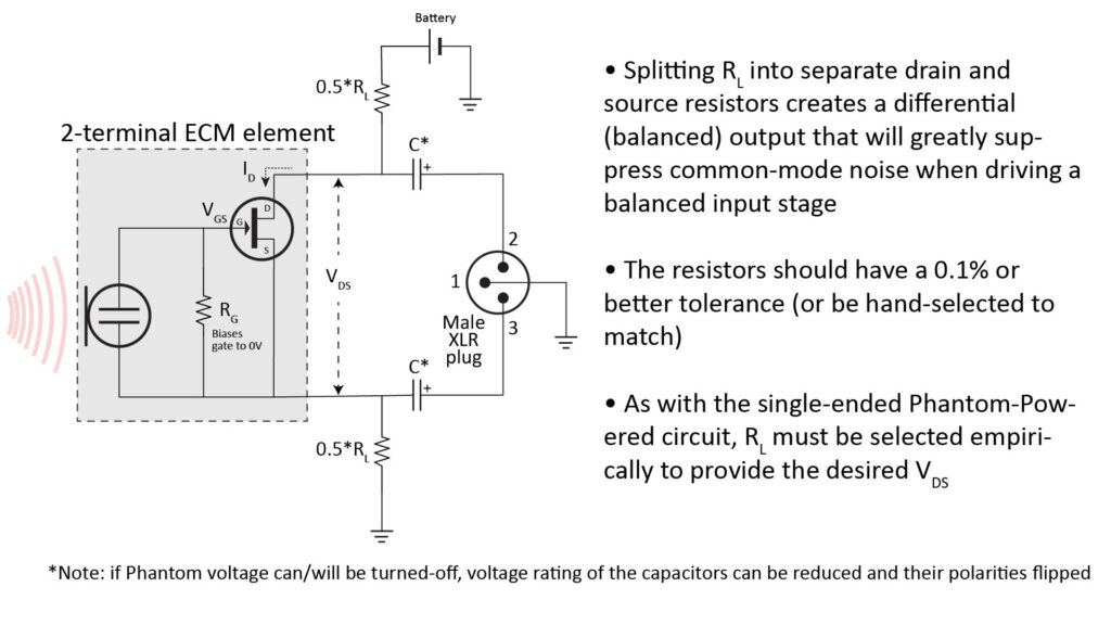
This doubles the number of resistors and coupling capacitors, but has the advantage of providing a fully balanced output.
Incidentally, if you’re familiar with FETs, you know that a source resistor in a conventional FET buffer provides negative feedback, reducing the gain. However, there is no negative feedback in the configuration of Figure 9, because an ECM’s electret condenser element is connected between the FET’s gate and source terminals, and not between the FET’s gate and signal ground. In fact, if the circuit of Figure 9 is used to drive a differential input stage, then the gain (and hence the microphone sensitivity) will be exactly the same as for the conventional two-terminal configuration of Figure 2.
A few things to keep in mind:
- The resistors should ideally have a tolerance of 0.1 percent, because any mismatch will unbalance the signals and reduce the common-mode noise rejection. However, I’ve found that 1 percent tolerance resistors will still provide considerable noise rejection.
- The capacitor orientation shown in the figure assumes that the Phantom voltage cannot or won’t be switched-off, and in that case, the coupling capacitors must have a sufficiently high voltage rating to withstand that voltage (as previously mentioned, a 60V rating is adequate for 48V PP). On the other hand, if the Phantom voltage can/will be switched off, the capacitor polarity should be flipped and the voltage rating can be reduced accordingly.
- In order to obtain the benefits of a balanced connection, the two load resistors must be located as close to the microphone element as possible, so that the cable carries fully balanced signals. With a studio mic, it’s usually easy to provide enough space in the microphone housing for all of the components of Figure 9 (including the battery and coupling capacitors). But for smaller mics (like lavalier and headset types), at least the larger components usually need to be packaged in a separate module, perhaps with a belt clip.
Using Phantom Power directly with a split load resistance
It’s possible to power the split-load-resistance circuit of Figure 9 from PP (thereby eliminating the need for the battery) by using a Zener diode and/or linear voltage regulator. However, that’s obviously a bit more complex.
Using a differential line-driver with a separate power supply
Another way to implement a balanced connection between an ECM-based microphone and a PP-enabled balanced input is with a differential line-driver located close to the microphone. The line-driver takes the single-ended output of the basic ECM circuit of Figure 2 and converts it into a fully balanced output.
It’s possible to power the line-driver by PP using a Zener diode. However, because of the limited current capacity of PP, it’s better to use a dedicated power source like a battery.
The advantage of this approach over the split load-resistance approach of Figure 9 is that it can provide signal buffering (and optionally amplification) to reduce the output impedance. This enables it to drive a longer cable with a greater signal-to-noise ratio and better high-frequency response. Of course, it’s also a bit more complicated than the simple split load-resistance approach of Figure 9, and the added performance isn’t always noticeable. So, I’ll generally use this approach only for microphones that also include other active circuitry (like active filters).
I’ll link to the design of an ECM-based microphone using this approach here.
Using a pair of ECMs to make a figure-eight (bidirectional) microphone
As previously shown in Figures 5 and 6, the intended purpose of the differential amplifier in a balanced input stage is to suppress common-mode noise.
However, the differential amplifier can also be used for another purpose: to provide a figure-eight (bidirectional) polar pattern by subtracting the outputs of two physically-separated ECM elements. This is most easily done using a separate bias supply (such as a battery):
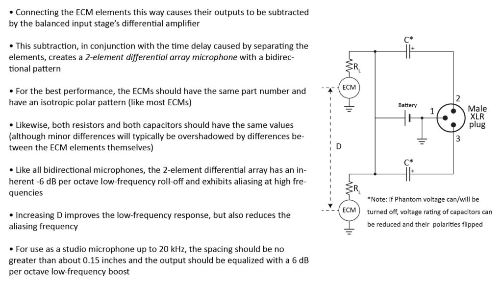
In addition to providing a bidirectional polar pattern, this configuration loads both PP input lines with exactly the same impedance, providing rejection of common-mode noise.
This configuration is known as a differential dipole array microphone, and many commercial bidirectional studio microphones work in exactly the same way—except that in this case, the subtraction is being performed by the differential amplifier built-in to the PP input, rather than by a differential amplifier built-in to the microphone housing.
Like all microphones with a bidirectional polar pattern, the mic of Figure 10 exhibits aliasing in the frequency response above a certain frequency determined by the microphone spacing D—and also exhibits a 6 dB per octave low-frequency roll-off below that frequency. We can avoid the aliasing problem by using a small enough D, and we can deal with the low-frequency roll-off by using electronic equalization (in real time or in postprocessing). Commercial figure-eight microphones do exactly the thing, although the equalization is sometimes done mechanically (by adjusting the mass of the diaphragm).
By the way, I cover differential array microphones (and array microphones in general) in-depth in How array microphones work.
Wiring-up an ECM element to make a usable microphone
How you wire-up an ECM element (i.e. the type of plug, plug pin assignments, and type of cable) will depend on your performance requirements and the type of device(s) you intend on driving with the completed microphone. My post on Microphone back-end design addresses this topic in detail, but the gist is that most DIY microphones will use one of the following:
- The ECM element is wired directly to a plug compatible with the most common PiP-enabled 3.5mm TRS format (as shown previously in Figure 4). This requires a “single-conductor” shielded cable (typically referred to as an “unbalanced” cable); such a cable actually has two conductors (the inner wire and the shield).
- The ECM element is wired directly to an XLR plug compatible with standard balanced microphone inputs (such as previously shown in Figures 8 or 9). This requires a two-conductor shielded cable (which actually has three conductors, counting the shield).
- The ECM element is wired to plug into an interface module, which in turn is wired to plug into a downstream microphone input (usually either a PiP-enabled TRS input or a PP-enabled XLR input). This interface-module approach is useful when the microphone assembly must be kept as small as possible (e.g. for a lavalier or headset mic) but includes an optimized bias supply (such as shown in Figures 5 or 9) or active electronics. In this case, the wiring between the ECM element and the interface module typically uses a non-standard format, such as this 3-conductor format or this 4-conductor format.
As far as the cable itself is concerned, I always use Mogami bulk microphone cable of the appropriate type, available from Markertek or Parts Express.