Here’s everything you need to know before building or buying a parabolic microphone, including key design considerations and the kind of performance you can realistically expect. I cover all that—and a lot more—in this post.
How parabolic microphones work
A parabolic microphone consists of a microphone element mounted at the focus of a parabolic reflector. The reflector increases the microphone’s pick-up range in two ways:
- It provides acoustic gain for sounds arriving along the reflector’s axis of symmetry.
- More importantly, the acoustic gain decreases as the sound’s angle of arrival deviates from the axis of symmetry. This attribute is called directivity, and it’s the key to long-range pick-up because it attenuates off-axis noise that competes with the target sound.
This is possible because, as shown in Figure 1, a parabolic reflector (or “dish”) has the property that a sound wave striking it from the on-axis direction—regardless of where on the dish it strikes—will be reflected to a specific focal point determined by the shape of the dish. Therefore, if a microphone element is mounted at that focal point, it will receive all of the acoustic power received by the entire dish, which results in significant acoustic gain and directivity:

The Directivity (D), sometimes also called the gain G, is defined as the ratio of the on-axis response to the response averaged over all directions. Directivity is often expressed as the Directivity Index (DI), which is the ratio D in dB.
Note that the directivity D and gain G provided by a dish are proportional to the square of the ratio of its diameter to the wavelength. Thus, the gain increases with increasing frequency, which means that the output of a parabolic microphone has a high-pass characteristic.
The term ε in the directivity/gain equation of Figure 1 is an efficiency factor that accounts for the facts that the shape of the dish might not be perfectly parabolic, the microphone diaphragm may not be positioned at the exact focal point of the dish, the microphone mount might obscure some of the dish, and other factors. Most online sources cite an an efficiency factor of around 0.5 of 0.7 for a well-designed microphone; I generally use 0.6. However, if there are issues with the design or implementation, an assumed efficiency of even 0.5 can be optimistic.
The focal length f is the distance from the vertex of the reflector to the focus, where the sound is concentrated and where the microphone element should be mounted. The focal length is determined just by the diameter and depth of the dish (assuming that it has a true parabolic shape).
How parabolic microphones are used
One reason is that not all dishes that appear to be parabolic actually are parabolic. Some DIY “parabolic” microphones use non-parabolic reflectors like mixing bowls or trash-can lids, and those microphones typically have gains lower than predicted by the equation in the chart, especially at higher frequencies. In fact, such microphones operate more like horns or boundary-layer microphones instead of parabolic microphones.
Parabolic microphones are best-known in the context of sports, surveillance, and bird-watching applications, but there are many other use-cases such as those listed in the following table:
| Application scenario | Typical target sound characteristics | Typical ambient noise characteristics | Required signal fidelity | Required range |
|---|---|---|---|---|
| General use (video-conferencing, social media, general video-production) | “Normal” voice model (70 dBA at 1 foot from source) | “Indoor medium” noise model (35 dBA) | 100 percent speech intelligibility, but significant audible noise acceptable (signal quality comparable to the output of a properly-used shotgun microphone) | 2 – 12 feet |
| Sports | “Shout” voice model (100 dBA at 1 foot from source) | (Coming soon) | At least 75 percent speech intelligibility; high level of audible noise acceptable | Varies; typically 80 feet (half the width of a football field) |
| Surveillance | “Normal” voice model (70 dBA at 1 foot from source) | “Outdoor rural” noise model (37 dBA); applies only under low-wind conditions | At least 75 percent speech intelligibility; high level of audible noise acceptable | Varies; generally limited by capabilities of microphone to less than 100 feet |
| Search and rescue | “Shout” voice model (100 dBA at 1 foot from source) | “Outdoor rural” noise model (37 dBA); applies only under low-wind conditions | Varies from 0 percent speech intelligibility (to detect presence of lost party) to 75 percent intelligibility | As long as possible |
| Capturing higher-frequency animal sounds | Depends on species | “Outdoor rural” noise model (37 dBA); applies only under low-wind conditions | Varies; typically comparable to fidelity requirements for general-purpose voice capture | Varies; generally limited by capabilities of microphone and required fidelity to less than 200 feet |
| Machinery diagnostics (such as for gas leak or noisy-bearing detection) | Varies; typically ultrasonic or at the upper edge of the audio bandwidth | Varies | Varies; typically requires a narrowband signal-to-noise ratio of 6 dB to detect presence of leak | Varies; typically less than 10 feet |
Like the shotgun microphone, the parabolic microphone is often the subject of unrealistic performance expectations. The application scenario in which a parabolic microphone is least likely to meet its performance expectations is Surveillance. Capturing fully intelligible voice at normal conversation volumes from long ranges (100 feet or more) can require a surprisingly large dish—one that would be very difficult to conceal. I’ll address realistic range expectations against conversational voice in more detail later.
On the other hand, the use-case for which parabolic microphones are most underappreciated is the General scenario of Table 1. There are many more practical applications for capturing sound at modest ranges (2 to 12 feet) than the long ranges typically associated with parabolic microphones (~100 feet). In fact, a small parabolic microphone can be much more cost-effective than a shotgun microphone in such shorter-range applications. By the way, that’s a topic I address extensively in The Klover MiK 09: can a small parabolic microphone outperform a shotgun microphone?.
Parabolic microphone limitations
Probably the most significant limitation of parabolic microphones is that their useful ranges are less than might be expected, but we’ll get to the question of useful range later.
There are also three other limitations which can become significant in certain applications:
- Poor performance in rain or high winds (which applies to all types of microphones, but especially to parabolic types). Rain and high winds don’t just dramatically increase the broadband ambient noise level, they also interact with the parabolic microphone itself to create additional noise. Unfortunately, there’s very little that can be done about this. Devices such as a foam rim mounted on the periphery of the dish—or a mesh screen that covers the entire dish aperture—can provide a modest amount of noise mitigation, but parabolic microphones should still be regarded as strictly fair-weather devices when used outdoors.
- Need for accurate aiming. The larger the diameter of a parabolic reflector, the narrower its beam-width for a given frequency—so the more accurately it must be aimed at the source for the best high-frequency response.
- Need for frequency equalization. A parabolic microphone has an inherent 6 dB per octave high-pass characteristic which should ideally be equalized when capturing a broadband signal.
Poor performance in rain or high winds
Excessive noise due to wind and rain is a potential problem for any kind of microphone used outdoors, and the parabolic mic is especially bad in this regard because of its large edge circumference and surface area. The edge of the dish acts as a noise source due to vortex-shedding from wind, while the surface acts as a noise source from the impact of raindrops. Some semi-flexible dishes also generate a small amount of noise through aeroelasticity in the presence of wind. And these effects are over and above the increased ambient noise in general due to wind and rain.
At least two manufacturers of parabolic microphones offer accessories to minimize weather-induced noise:
- Wildtronics LLC supplies foam windscreens for its microphone elements, which it claims allow use in winds of up to 10 to 12 MPH. They also offer a mesh windscreen for their parabolic microphones that covers the entire dish and is claimed to allow use in winds of up to 20 MPH.
- Telinga offers a fleece windscreen accessory for their parabolic microphones that also covers the entire dish, but does not provide a claimed maximum windspeed spec.
I haven’t tested a Wildtronics dish with the accessory windscreen, so I can’t comment on its effectiveness. However, I know from personal experience that, even with extensive wind-screening, capturing high-quality sound with a parabolic microphone is a challenge with average wind speeds over 10 MPH.
However, wind screens like those offered by Wildtronics and Telinga do provide a definite reduction in wind-induced noise, and should certainly be considered for outdoor use.
Need for accurate aiming
The performance benefits of directivity also come at a price: a high-directivity microphone must be pointed exactly at the source of the desired sound for maximum performance. How exactly? That depends on the microphone’s beamwidth.
A microphone’s beamwidth is effectively its acoustic Field of View (FoV), analogous to the optical FoV of a camera. And, like a camera’s FoV, the FoV of a parabolic microphone varies with wavelength.
In the case of a camera, the percentage variation in wavelength over the visual spectrum is small enough (only about 60 percent) that it can be mitigated through the the use of a achromatic lens design, so that the variation in FoV is negligible. Thus, a photographer doesn’t have to worry about different FoVs for blue and red objects.
With audio, on the other hand, the wavelength varies by an enormous 1000:1 over the whole 20 Hz to 20 kHz bandwidth, and there is no such thing as a “constant-directivity parabolic microphone.” Therefore, the beamwidth of a parabolic microphone also varies by 1000:1 over the whole audio bandwidth: the beamwidth is essentially 360 degrees at 20 Hz, decreasing to a far smaller value (depending on the dish diameter) at 20 kHz.
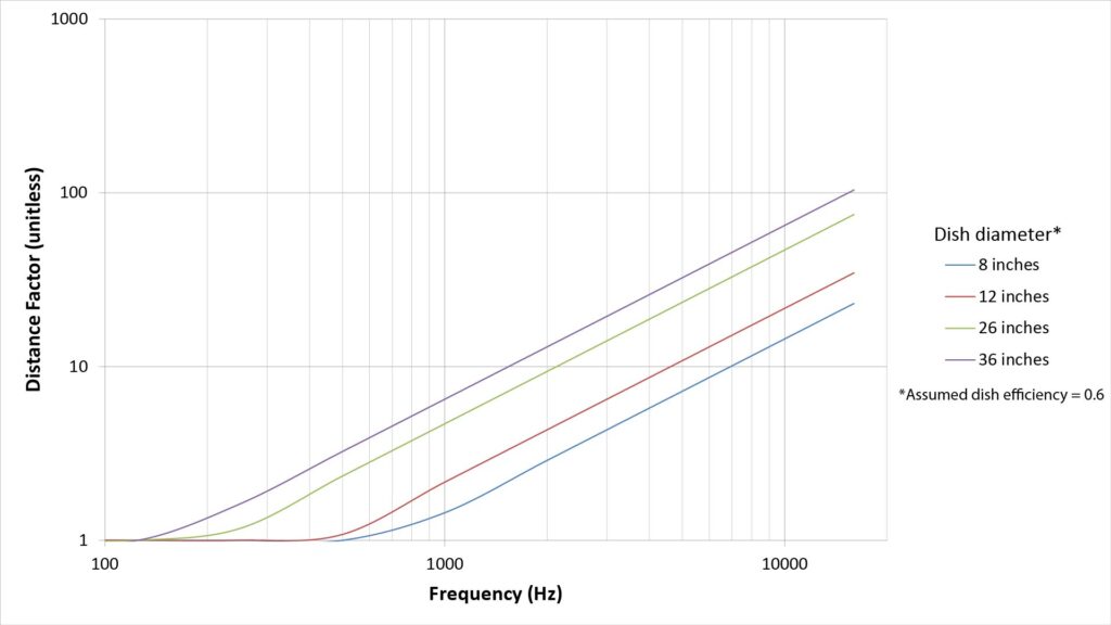
The following figure plots the half-power beamwidth versus frequency for several parabolic dish diameters:
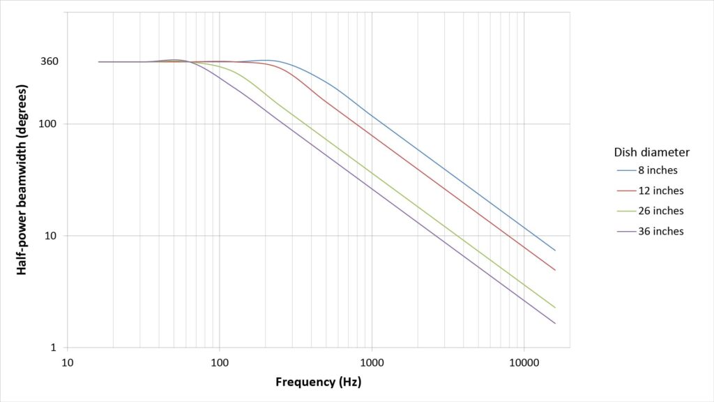
For reference, a 250 mm telephoto lens on a 35 mm camera has an FoV of about 10 degrees. With a 26-inch dish, the beamwidth remains greater than 10 degrees only up to about 4 kHz, dropping to just 2 degrees at 20 kHz.
In fact, the beamwidth of a typical parabolic microphone is so narrow at 20 kHz that it’s practically impossible to aim it accurately enough to capture such frequencies.
Fortunately, we don’t need a bandwidth that extends to 20 kHz for most applications where the directivity of a large dish is necessary. For example, picking-up voice for a surveillance application might require a bandwidth that extends to just 4 kHz, while capturing bird songs might require a bandwidth that extends to 8 kHz.
However, even at those relatively lower frequencies, the beamwidth of a parabolic microphone intended for long-range use will be narrow enough to make aiming a challenge, especially if the source of the desired sound isn’t stationary.
Need for frequency equalization
Per Figure 1, the gain of a parabolic microphone varies inversely with the square of the wavelength (and thus directly with the square of the frequency) of the sound being captured. This means that a parabolic microphone acts like a first-order high-pass filter, with a response that rises at 6 dB per octave with increasing frequency:
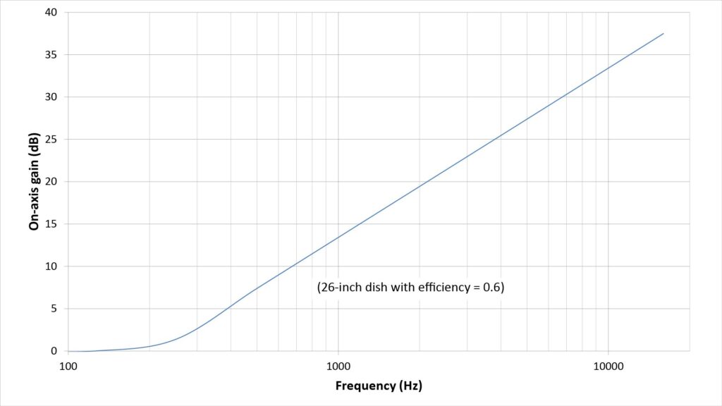
Therefore, if a parabolic microphone is being used to capture sounds that have significant bandwidth (such as voice, music, and bird songs), the output should typically be equalized to flatten the response.
This equalization can be done by boosting the low frequencies (positive equalization), attenuating the high frequencies (negative equalization), or a combination of both. The gain of a parabolic microphone permits negative equalization to be used at higher frequencies, which preferred because it typically results in a significantly higher signal-to-noise ratio.
If correctly equalized, then the fidelity of a parabolic microphone’s output isn’t necessarily inferior to that of any other microphone. In fact, lack of proper equalization is a major cause of the parabolic microphone’s undeserved reputation for poor fidelity.
However, there’s another reason for that bad reputation: if a parabolic microphone is used at the edge of its range capabilities, then of course the output will be noise. But that isn’t the fault of the microphone; it’s due to the laws of physics.
What’s the maximum useful range of parabolic microphones?
Parabolic microphones have the longest range for their size of any type of long-range microphone (check out my post on how long-range microphones work for an in-depth comparison).
But what is the maximum range of a parabolic microphone? That depends not just on the diameter of the parabolic reflector, but also on the characteristics of the sound to be picked-up, the characteristics of the ambient noise, and the required quality of the microphone output signal. The range of any given parabolic microphone can vary wildly depending on those variables.
In fact, getting an accurate estimate of the range of any microphone is a fairly complicated endeavor, which we’ll get into later. For now, let’s look at a relatively simple way to get rough estimate of the maximum range of a parabolic microphone.
Approximating parabolic microphone range via the Distance Factor (DF)
As I explain in my post on how long range microphones work, directivity is a key enabler for picking-up sound at long distances. That’s because directivity is the only thing that can directly reduce the effects of the ambient noise that would otherwise mask the faint target sound.
The conventional way of estimating the range extension provided by directivity is the Distance Factor (DF). To understand the concept of the DF, we must first understand the concepts of free-field propagation and inverse square losses.
Free-field propagation
A sound wave that is free to expand spherically at it travels away from its source is said to be propagating in a free-field. Perfect free-field propagation never occurs in real-life, but it’s a good approximation for how sound travels in open areas.
Inverse-square losses
The surface area of a sphere is 4πR2, where R is the radius. Therefore, because a sound wave expands spherically when it’s propagating in a free-field, the sound pressure decreases with the square of the distance it travels. This is called the inverse-square law.
Inverse-square losses are the dominant—but not the only—cause of signal attenuation in free-field propagation. Another signal-loss effect is atmospheric attenuation, but that’s usually significant only at higher frequencies and at long ranges under humid conditions. It’s therefore usually only a minor factor in most practical parabolic microphone applications.
The Distance Factor (DF) defined
With that background, consider two microphones that are both attempting to pick-up the same target sound, propagating under free-field conditions, in the same ambient-noise environment:
- Microphone A is non-directional and therefore has a Directivity D0 of 1. Assume that Microphone A is able to pick-up the target sound with adequate signal quality at a range R0.
- Microphone B is otherwise identical except that it has a directivity D1 greater than 1. Because of its directivity, microphone B is able to pick-up the target sound with adequate signal quality at a greater range R1.
The DF is then defined as the ratio of R1 to R0. It represents the increase in range at which the reduction in ambient noise due to directivity is exactly compensated by the additional inverse-square losses in the target sound.
Because of the inverse-square law, the reduction in the target sound for the increase in range from R0 to R1 is (R1/R0)2, or DF2. Meanwhile, the reduction in the ambient noise is equal to the Directivity D.
Thus, the DF is equal to the square-root of the directivity.
Finding the Distance Factor of a Parabolic Microphone
From Figure 1, we know that the directivity of a parabolic reflector can be found as follows:
- D = ε(πd/λ)2, where ε is the dish efficiency, d is the dish diameter, and λ is the wavelength
Since the DF is the square-root of the directivity, it can be found as follows:
- DF = sqrt(ε)*πd/λ
We can express the DF in terms of frequency instead of wavelength:
- DF = sqrt(ε)*πdf/c, where f is the frequency and c is the speed of sound
The DF thus scales proportionally with both the diameter of the parabolic reflector and the frequency of the sound:
Addressing the frequency dependence of the Distance Factor
The frequency dependence presents a problem in using the DF to estimate the range of parabolic microphones. The audio bandwidth extends from 20 Hz to 20 kHz, which is a range of 1000:1. Since the DF scales with frequency, the DF also varies by range of 1000:1 over the audio bandwidth. So, at which frequency do we estimate the range?
That depends on the type of sound we’re trying to capture:
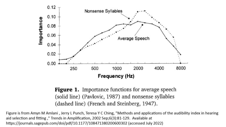
- If the target sound is voice, then the DF at 2 kHz is a reasonable approximation of the effective DF over the entire voice bandwidth for good intelligibility.
- If the target sound is music, then the “best” frequency at which to evaluate the DF depends on the required fidelity of the output signal. It could range from 2 kHz for poor fidelity down to as low as 200 Hz for reasonably good fidelity.
- Obviously, if the target sound has a very narrow bandwidth (as is the case for some insect vocalizations), then the DF should be evaluated at the center frequency of the sound’s bandwidth.
If you had to pick a single frequency at which to evaluate a parabolic microphone’s performance without a specific application in mind, it would probably be 2 kHz—and that’s what I usually assume when using the DF for rough approximations of maximum range.
The following chart shows the DF at 2 kHz as a function of dish diameter, assuming a typical efficiency factor of 0.6:
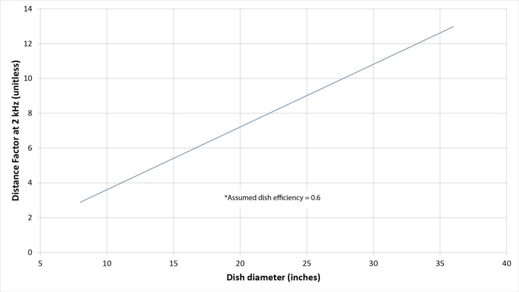
When most people see this curve, they’re surprised at how small the DF is for a standard-sized parabolic reflector (of about 2 feet in diameter. The DF is less than 10, which doesn’t seem like much of a range extension over a conventional studio microphone.
Using the Distance Factor to estimate the range of a parabolic microphone
Per the preceding discussion, we can easily determine the DF from the dish diameter, the assumed dish efficiency, and the selected frequency.
But since the DF is a unitless factor and not a range in feet or meters, how do we use it to actually determine the range of a parabolic microphone?
The best way is by doing some microphone testing without the parabolic reflector
As previously mentioned, the range of any microphone depends heavily on the characteristics of the target sound, the characteristics of the ambient noise, and the required signal quality—none of which are addressed by the DF.
So, the best way to use the DF is by using it as a multiplier on the measured range of a non-directional microphone that’s used to capture the same sound, in the same ambient noise environment, as the envisioned parabolic microphone:
- Ideally, this test microphone would have exactly the same self-noise as the microphone element that would be used in the subject parabolic microphone, but that’s not critical. Any reasonably quiet microphone with a non-directional (isotropic) polar pattern, such as a $20 lavalier mic, will suffice.
- Ideally, the test microphone would be plugged into the same field recorder or headphone amplifier that would be used with the envisioned parabolic microphone, but that’s not critical. Any field recorder or headphone capable of accepting the microphone’s output will suffice (assuming that the input stage has sufficient sensitivity and isn’t excessively noisy).
- If using a field recorder, the microphone is then positioned close to the source of the target sound and then slowly moved away as the distance is counted-off every foot or so (so that the count can heard in the recording). If using a headphone amplifier, the microphone is slowly moved away until the signal quality drops to a barely acceptable level.
- The maximum range at which the signal quality is still acceptable is then multiplied by the DF to obtain the expected range of the envisioned parabolic microphone.
Using the DF to estimate the range without testing
The DF can also be used to estimate the range of a parabolic microphone without testing. However, that’s a much less accurate way to use the DF because the actual range is influenced so heavily by factors other than directivity. Here are some base ranges (to be multiplied by the DF) that I use for quick range predictions without testing:
| Required output signal quality | Base range for reference isotropic microphone (assumes target sound and ambient-noise profile of “General” scenario of Table 1) |
|---|---|
| High | 0.5 feet |
| Medium (100 percent voice intelligibility; some audible noise) | 1 foot |
| Low (100 percent voice intelligibility; substantial audible noise) | 2 feet |
| Very low (75 percent voice intelligibility) | 6 feet |
When multiplied by the DF, the base ranges of Table 2 enable rough approximations of parabolic microphone range that are accurate enough for many purposes.
Note that the base ranges given in Table 1 vary by 12:1 based on the required output signal quality. And so, therefore, will the implied parabolic microphone ranges when the base ranges are multiplied by the DF.
This illustrates an important fact of life about parabolic microphone range: ranges greater than a few tens of feet with a typical dish will necessarily result in far poorer signal quality than would be acceptable in other microphone applications.
The DF does not comprehend parabolic microphone gain
One limitation of the DF is that the only microphone attribute it considers is directivity. From Figure 1, we know that a parabolic microphone provides directivity by boosting signals in the on-axis direction, which means that it also provides on-axis gain. This is one thing that separates the parabolic microphone from the shotgun microphone, which provides directivity by attenuating off-axis sound rather than by boosting on-axis sound (by the way, I analyze the shotgun microphone extensively (more extensively than any other source I’ve found on the web) in How shotgun microphones work).
However, since a parabolic microphone’s directivity and gain are equal (per Figure 1, we’d get the same value of DF if the DF equation were based on gain instead of directivity.
In fact, that’s a perfectly valid way to view the concept of the DF as applied to parabolic microphones: instead of the increased range coming from a reduction in ambient noise, it comes from a boosting of the faint target sound.
But because the DF doesn’t account for the fact that a parabolic microphone provides both directivity and gain, it does significantly underestimate the achievable range under certain conditions.
Specifically, the benefit of gain increases with increasing directivity, increasing microphone self-noise, and decreasing ambient noise. Unfortunately, the DF approach can’t comprehend most of these variables.
Better ways to estimate the range of a parabolic microphone
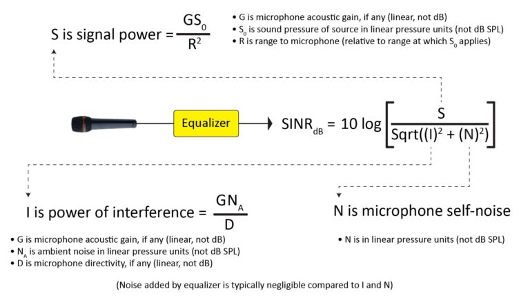
More accurate (but also more complex) ways to estimate microphone range are enabled by the concept of the Signal-to-Interference-plus-Noise Ratio (SINR). Range estimates based on the SINR comprehend all of the variables that determine microphone range, and not just the directivity.
A full discussion of the SINR and how it can be used to estimate microphone range is beyond the scope of this post, but see the following if you’re interested in the topic:
- Predicting microphone performance—Part 1: what is microphone SINR?
- Predicting microphone performance—Part 2: using the SINR
- Predicting microphone performance—Part 3: microphone range prediction
The first two posts introduce the SINR, while the third describes several SINR-based methods for microphone range prediction. The range estimates given in the rest of this post were obtained using the most sophisticated of these methods, which is based on SINRs evaluated in eleven frequency sub-bands across the audio spectrum. This enables it to comprehend not just the frequency-dependence of directivity and gain, but also differing spectral characteristics of the target sound and ambient noise.
Parabolic microphone range projections for the “General” scenario
The maximum range of a parabolic microphone for a given required signal quality is determined by the target sound level and spectrum, the ambient noise level and spectrum, and the microphone self-noise— all in addition to the dish diameter. As a result, the range of a parabolic microphone of any given dish diameter will vary over a wide range for each of the 6 application scenarios of Table 1.
However, this post is already going to be more than long enough without including range projections for all 6 of those application scenarios. So this section provides SINR-based range estimates for what I think is the most representative scenario: the General scenario:
- The assumed target sound in the General scenario is human voice at a normal conversational volume of 70 dBA at 1 foot (see Predicting microphone performance—Part 1: what is microphone SINR? for the assumed spectral characteristics). This is the same target sound model assumed in three of the other application scenarios of Table 1, including the Surveillance scenario.
- The assumed ambient noise in the General scenario is what I call the Indoor Medium noise profile with a broadband SPL of 35 dBA (see Predicting microphone performance—Part 1: what is microphone SINR? for the assumed spectral characteristics). The Indoor Medium noise profile is very similar to the Outdoor Rural profile assumed in my Surveillance scenario.
So, range estimates based on the General scenario will be very close to those based on the Surveillance scenario—and those two scenarios probably account for the bulk of parabolic microphone applications involving pick-up of human voice.
Assumed microphone self-noise
The following range estimates are based on a microphone self-noise of 14 dBA. That’s a respectably low self-noise, and the reason for assuming it for the following projections will become clear when I discuss microphone element considerations a bit later in this post.
Parabolic microphone signal quality versus range for intelligibility-sensitive applications
Many parabolic microphone applications are aimed at picking-up voice at long ranges, and in most such applications it’s the intelligibility of the output signal—and not its fidelity—that’s important. Specifically, it’s acceptable to sacrifice some SINR below 2 kHz for the sake of increased range.
I’ve developed a SINR-based signal quality metric for such intelligibility-sensitive applications that I call the Intelligibility Index (II). The following figure plots the II versus range for various parabolic microphone dish diameters, assuming a dish efficiency of 0.6 and a microphone self-noise of 14 dBA, for the target sound and ambient noise assumptions of the General scenario:
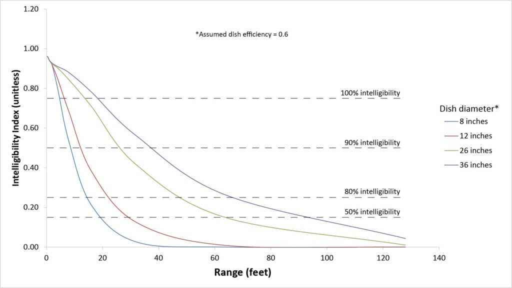
Of the dish diameters shown in Figure 6, the 26-inch dish is probably most representative of a typical full-sized parabolic microphone. Note that with such a dish diameter, ranges of more than 60 feet require settling for a speech intelligibility of less than 50 percent speech. That’s often still high enough to understand what’s being said (due to contextual cues), but it’s certainly not high-quality voice; there will be plenty of audible noise at the lower frequencies.
Parabolic microphone signal quality versus range for fidelity-sensitive applications
Applications that stress audio fidelity require greater SINR—over a wider bandwidth—than intelligibility-sensitive applications. I’ve developed a signal quality metric for such applications that I call the Fidelity Index (FI). The following figure plots the FI versus range for various parabolic microphone dish diameters, assuming a dish efficiency of 0.6 and a microphone self-noise of 14 dBA, for the target sound and ambient noise assumptions of the General scenario:
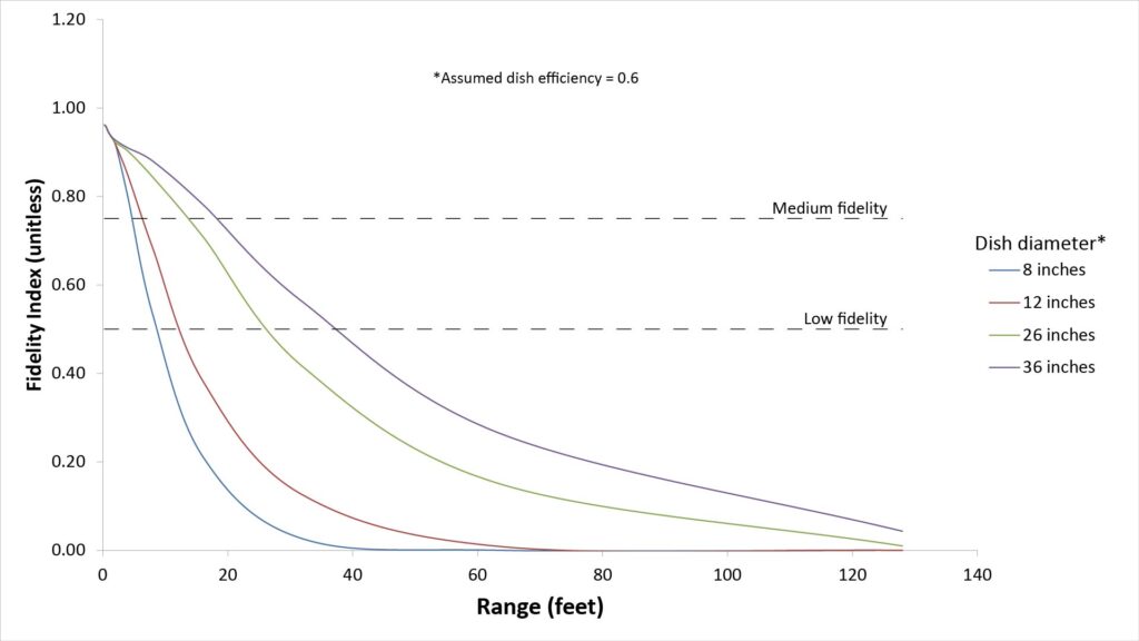
Note that even the 36-inch dish has a surprisingly short range if at least a medium fidelity output signal is needed—just 20 feet. That’s because the fidelity metric values the SINR at bass frequencies, at which even a 36-inch dish can’t provide much directivity or gain.
Parabolic microphone range versus required signal quality
Another way to visualize the range projections of Figures 6 and 7 is to show the ranges for various levels of required signal quality, like this:
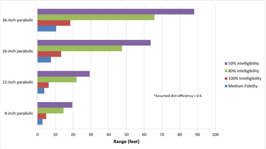
Some observations about parabolic microphone range
Parabolic microphones have the longest useful range for their size of any type of long-range microphone. But as the projections of Figures 6 — 8 show, that range can be surprisingly short in absolute terms even if a substantial compromise in signal fidelity can be tolerated.
Ranges can be much longer in other scenarios
While these “General scenario” ranges are fairly representative of the useful ranges of parabolic microphones in typical applications, the ranges can be substantially longer when capturing louder or higher-frequency sounds, or in environments with lower ambient noise levels.
In fact, under ideal conditions, ranges could exceed those projected for the General scenario by a factor of 10 or more, which is more in line with the claims made by parabolic microphone manufacturers.
One application in which you can regularly expect such ideal conditions is in capturing the songs of small birds in very quiet outdoor settings. The fundamental and harmonic frequencies of bird vocalizations varies inversely with body mass, so smaller birds are ideal subjects for parabolic microphones. Ranges of 100 feet or more are easy achievable in such circumstances.
Another application in which very long ranges are achievable is Search And Rescue (SAR) in very quiet rural environments. Not only is the ambient noise level relatively low, but the target sound (shouts from the Lost Party, or LP) is up to 30 dB louder, and shifted higher in frequency, than assumed in the General scenario. This combination of factors can yield ranges in the hundreds of feet for a 2-foot diameter dish.
Relative range scales with dish diameter
Per the equations of Figure 1, the gain and directivity of a parabolic microphone vary with the square of the dish diameter, while the inverse-square law says that the target sound level drops with the square of the distance. That means that the maximum range of a parabolic microphone should scale directly with the dish diameter.
That indeed turns out to be the case. We can see that by plotting the ranges of Figure 8 against the dish diameter, as shown in the following figure:
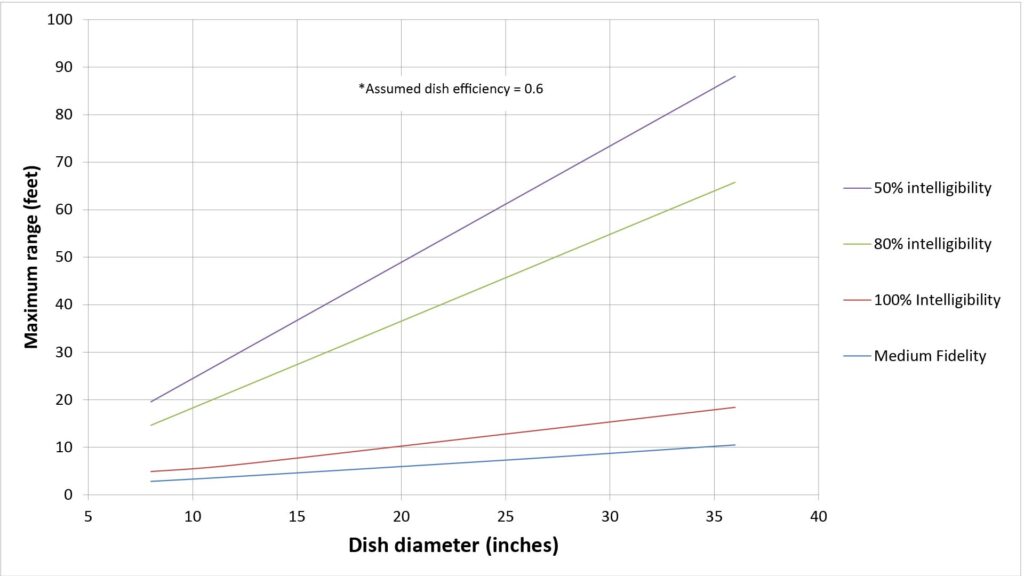
This rule-of-thumb is valid regardless of the application scenario: the relative range of a parabolic microphone is proportional to the diameter of its dish.
Parabolic microphones: buy or DIY?
A complete parabolic microphone consists of one or more microphone elements, a parabolic reflector, a means of mounting the microphone element(s) at the focus of the reflector, an optional preamplifier and/or headphone amplifier, and a means of hand-holding the complete assembly or mounting it on a tripod.
If you want such a complete parabolic microphone, there are three ways to get one:
- You can buy a complete parabolic microphone that includes a microphone element (and, optionally, an amplifier).
- You can buy a parabolic microphone that is almost complete except for the microphone element and electronics.
- You can build it yourself.
A parabolic microphone makes a great DIY project, for at least 4 reasons:
- the underlying principles are interesting but not hard to grasp,
- construction isn’t prohibitively difficult,
- rather than being just a science project, the completed project can actually be very useful, and
- material costs are usually far less than the price of comparable commercial parabolic microphones.
For that reason (and because DIY microphones are the focus of this site), I’m devoting the next section of this post to key considerations in the design of parabolic microphones. While this information is essential for the DIY parabolic microphone builder, it should also be useful in choosing the right parabolic microphone for those who want to buy one off-the-shelf.
Parabolic microphone design considerations
In addition to the all-important dish diameter, there are three other considerations in choosing a dish (reflector) for a parabolic microphone:
- The dish’s focal-length-to-diameter (f/D) ratio
- The accuracy of the dish’s parabolic shape
- The smoothness of the dish’s inner surface
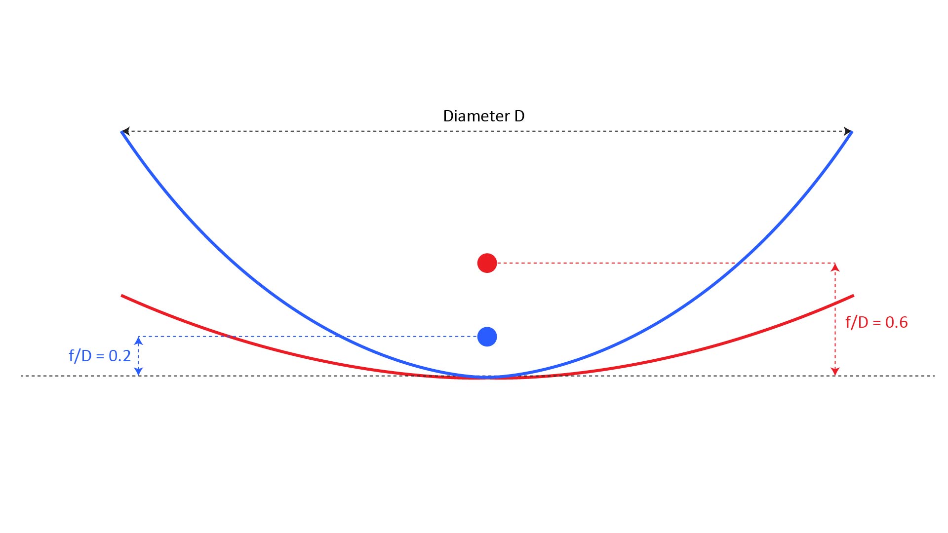
The f/D ratio
As previously shown in Figure 1, the focal length of a true parabolic dish can be found as f = D2/16d, where D is the dish diameter and d is the depth of the dish. The shape of a parabolic dish is completely determined by the ratio of focal length to diameter, f/D, which ranges from around 0.2 to 0.6. As shown in Figure 10, a deep parabolic dish will have a short focal length and a small f/D ratio, while a shallow dish will have a long focal length and a large f/D ratio:
The f/D ratio determines the microphone element polar pattern necessary to take full advantage of the dish gain. This is because the microphone’s polar pattern should be just wide enough to capture sounds from the entire inner surface of the dish—but no wider, in order to minimize pickup of off-axis noise
So, the microphone pattern should theoretically be wide when the f/D ratio is low, and narrow when the f/D ratio is high.
For example, you can see from Figure 10 that, with an f/D ratio of 0.6, the focus is outside the dish’s mouth. Thus a microphone with an isotropic pattern would pick up ambient noise from the sides of the dish, favoring a cardioid pattern.
On the other hand, a low f/D ratio such as 0.2 obviously favors an isotropic pattern, because a cardioid would fail to capture most of the sound collected by the dish. But using an isotropic microphone creates another issue (regardless of the f/D ratio): an isotropic microphone will pick up direct on-axis sound as well as sound reflected by the dish, and interference between the direct and reflected sound can affect the frequency response. This is discussed more in the microphone section below.
A second implication of the f/D ratio is that it influences the sensitivity of gain to errors in the shape of the dish and position of the microphone. A dish with a low f/D ratio will be more sensitive to errors than one with a high f/D ratio. However, I’ve found that good results at audio frequencies can be obtained with dishes with relatively low f/D ratios, so I don’t consider this to be a major factor in choosing a dish for audio applications.
A third, and possibly the most significant, implication of the f/D ratio is that it influences the required mounting structure for the microphone. A dish with a higher f/D ratio will need larger mounting structure because the focus will be outside the mouth of the dish. This can also make the finished parabolic microphone system bulkier, more fragile, and more difficult to handle and store, than one using a dish with a smaller f/D ratio.
For the latter reason, I’ve found that dishes with lower f/D ratios are preferable for use in parabolic microphones, but that’s not a firm requirement.
For maximum gain, the dish should be truly parabolic
The range predictions given earlier in this post assume a dish efficiency of 0.6, which is typical of actual parabolic microphones. However, achieving an efficiency of 0.6 requires a real parabolic dish (not just one that looks like it might be parabolic), as well as accurate placement of the microphone diaphragm at the focal point of the dish.
Based on my testing, the center of the microphone diaphragm must be within about a tenth of a wavelength of the focal point at the highest frequency of interest to avoid a significant loss in gain, and the same precision probably applies to the dish shape. In other words, every point on the interior surface of the dish should probably be within about a tenth of a wavelength of a perfect parabolic shape.
For a parabolic microphone used only for voice, the maximum frequency of interest might be only 8 kHz. At 8 kHz, a wavelength is about 1.7 inches, so the error must be kept below about 0.17 inches to avoid a noticeable loss in gain. If the microphone will be used to capture higher-frequency sounds such as from bats or mosquitos, then the allowable error will be correspondingly smaller in order to achieve the full predicted gain.
For this reason, the performance of DIY “parabolic” microphones that repurpose items such as mixing bowls or trash-can lids as reflectors can be disappointing, especially at higher frequencies. Such reflectors can indeed provide some gain when capturing voice, but it will be less than achievable with a true parabolic dish.
How do you verify that a dish is truly parabolic?
As discussed in the next section, depending on the source of your parabolic dish, you might already be reasonably certain that it has a truly parabolic shape. But if you’re not sure, there are three ways to tell:
- You can make a quick check by taking a few measurements of the dish and comparing them to what would be expected from a true parabolic dish.
- If the dish is shiny, you can use the flashlight method.
- You can measure the output of a microphone to see if the dish has a sharp acoustic focus that provides significant gain.
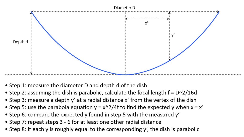
Measuring the dish
From Algebra 1 we know that all parabolas are defined by the equation y=x^2/4f, where y is the depth, x is the radial distance from the vertex, and f is the focal length. We also know that f = D2/16d, where D is the dish diameter and d is the depth at the deepest point (the vertex).
So, assuming that the dish we have is parabolic, we can first determine its focal length by measuring its diameter and depth. Then, we can measure the dish’s depth at a couple of radial distances from the center, and compare those depths to what would be expected from the parabola equation using the same focal length. If the measured depths are within a few tenths of an inch of the expected depths, the dish is mostly likely truly parabolic.
The flashlight method
If the dish we have is very shiny, then the flashlight method is an easy way to verify that it’s truly parabolic. Just place the lens of a flashlight inside the dish and move it along the centerline, while looking at the dish on-axis. If the dish is parabolic, you’ll be able to find a sharp focal point at which the entire dish surface suddenly lights-up evenly.
The microphone-on-a-stick method
You can monitor the output level of a small microphone to see if the dish has a sharp acoustic focus. You can even actually measure the dish’s acoustic gain, but that’s not as easy as it sounds.
The microphone-on-a-stick method requires four things:
- First, you need a small isotropic microphone element taped to a thin rod or stick that’s about as long as the dish’s diameter. A lavalier microphone will work if you don’t want to wire-up a bare microphone element.
- Next, you need some way to monitor the microphone’s output level. A field recorder with a level meter would work, as would an oscilloscope.
- You need a steady acoustic source. By far the easiest way to meet this requirement is with a smartphone running a signal-generator app (there are plenty of free signal-generator apps available if you don’t mind ads).
- Finally, you need some way to position the dish and smartphone so that they’re at least a couple of feet apart, with the smartphone along the dish’s center-line. Unless the dish you’re testing already has some kind of tripod mount, the easiest way to do this is to lay the dish on the floor, with the smartphone on a table above it.
Once this is all set-up, set the signal generator app to produce a tone of about 3 – 6 kHz, and move the microphone along the center-line of the dish to see if you can find a spot where the output rises sharply. If you can’t find such a spot, the test is over and the dish probably isn’t worth using.
If you can find such a spot, note the output level and repeat the test with the microphone in the same position without the dish. The difference is the gain provided by the dish, but possibly corrupted by standing-wave effects from the floor or other objects. If the gain is anywhere close (say within a few dB) of the predicted gain of a dish of that diameter, the dish is almost certainly good.
How smooth does the dish surface need to be?
It’s helpful if the dish has a smooth, shiny surface, because it enables “eyeball verification” that the dish is truly parabolic (using the flashlight technique described above).
However, a smooth, shiny surface isn’t essential for audio applications: while surface roughness will degrade the dish gain, it will do so only for wavelengths of about one order of magnitude greater than the amplitude of the roughness. A dish with a pebble-grain surface might have a roughness amplitude of a few hundredths of an inch, which should be more than smooth enough for voice. However, a parabolic microphone used to capture higher-frequency sounds could probably benefit from dish with a polished surface.
Sources of true parabolic dishes
Rather than buying a dish that you think might be parabolic—and then testing it to see if it is—it makes more sense to start with a dish that is very likely to be truly parabolic. There are three cost-effective ways to obtain a such a dish:
- Use an old satellite TV dish
- Buy a polished dish intended to focus light
- Buy a dish actually intended for parabolic microphones from a reputable source like Klover, Telinga, or Wildtronics.
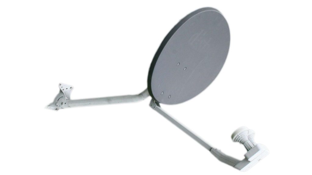
Repurposing a satellite TV dish
A satellite TV dish is almost guaranteed to have a parabolic shape that’s more than accurate enough for use in a parabolic microphone. That’s because the wavelength of RF at X-band or Ku-band (as used in modern satellite TV systems) is comparable to the wavelength of sound at 20 kHz.
A repurposed satellite TV dish also has the advantage that it will typically include a mounting structure for the dish itself and for the feed antenna, which can then be adapted to mount the microphone.
Used satellite TV dishes are widely available at low cost from yard sales or eBay, and some new satellite dishes manufactured in China are actually even less expensive. Most of these dishes are of the offset-feed (asymmetric) type and are 18 inches to 22 inches wide, but larger prime-focus (symmetric) dishes are also available in diameters up to 72 inches.
In fact, if you want a true parabolic dish larger than 24 inches, a new Chinese prime-focus satellite TV dish is probably the most cost-effective way to get it.
Prime-focus vs Offset Dishes
The parabolic dish previously shown in Figure 1 has its focus located along its axis of symmetry. In such a prime-focus dish, a microphone located at the focus will block some of the incident sound from reaching the dish. In a typical parabolic microphone, the microphone is small enough relative to the dish that this blockage will have only a small impact on performance.
However, in parabolic reflectors used to receive satellite TV signals, the antenna feed can be large enough relative to the dish that using a prime focus configuration can have a significant impact on performance. Therefore, many smaller satellite TV dishes use an asymmetric or offset feed configuration, in which the dish has different curvatures in the vertical and horizontal planes so the focus is offset from the dish’s mouth (where it doesn’t cause any blockage). However, the principle is the same: incident rays striking the dish anywhere on its interior surface are concentrated at the focus.
Satellite dishes typically have a high f/D ratio
Another potential issue with a repurposed satellite dish is that their f/D ratios are usually higher than optimal for a parabolic microphone. Satellite dishes have a higher f/D ratio because it favors a narrower antenna feed pattern, which is easier to achieve at millimeter RF wavelengths than the broader pattern needed by a dish with a lower f/D ratio. A high f/D ratio has three implications for use in a parabolic microphone:
- A cardioid microphone pattern must be used to minimize pickup of off-axis ambient noise (unless the system will be used exclusively in low-ambient-noise situations).
- Even with a cardioid pattern, the relatively long focal length will typically cause the microphone to be located far enough outside the dish that it will still pick up significant amounts of off-axis noise.
- For the latter reason, the whole assembly (dish plus microphone mount) will be much bulkier than if a dish with a smaller f/D ratio were used.
Satellite dishes are heavier than dishes intended for parabolic microphone use
Another issue is that, because they must withstand heavy wind and snow loads, satellite dishes are generally much heavier than necessary for use in portable parabolic microphones.
On balance, if you need a dish less than 24 inches in diameter, a repurposed satellite TV dish probably isn’t the best choice due to the high f/D ratio and heavy construction. On the other hand, if you need a large dish that doesn’t have to be easily transportable, than a large prime-focus satellite dish will be the most cost-effective solution.
Repurposing a dish intended to focus light
Parabolic dishes are used to focus infrared light in heating applications, to collect the sun’s rays for solar cooking or science projects, and as photography “beauty dishes” to concentrate the output of a flash lamp. These typically have a shiny inside surface and are available in sizes up to about 24 inches.
Like satellite dishes, these are guaranteed to be parabolic because they wouldn’t work at all for the intended purpose if they weren’t. It’s also easy to verify that a shiny parabolic dish has a sharp focal point using the flashlight method described above.
These dishes also typically have a lower f/D ratio than satellite TV dishes, which can help to minimize pickup of off-axis noise in a microphone application.
One issue with a repurposed light-focusing dish is that mounts for the microphone and the dish itself will generally have to be fabricated, so using such a dish for a DIY parabolic microphone involves more work than other types of dish.
Using a solar-collector dish
Polished aluminum parabolic dishes intended for solar collector applications are occasionally available on Amazon and from Scientifics Direct. They’re available in 12-inch, 18-inch, and 24-inch diameters, each with a f/D ratio of 0.25 (nearly ideal for a parabolic microphone). Retail prices range from $80 to $125, depending on size.
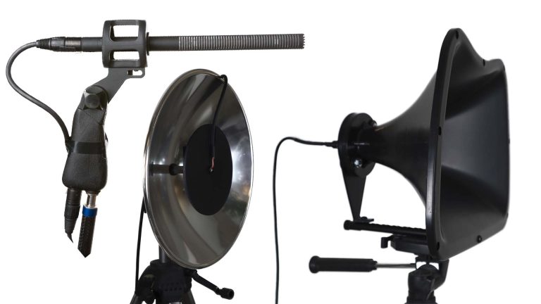
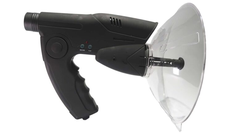
Here’s a DIY parabolic microphone made from such a 12-inch solar-collector dish:
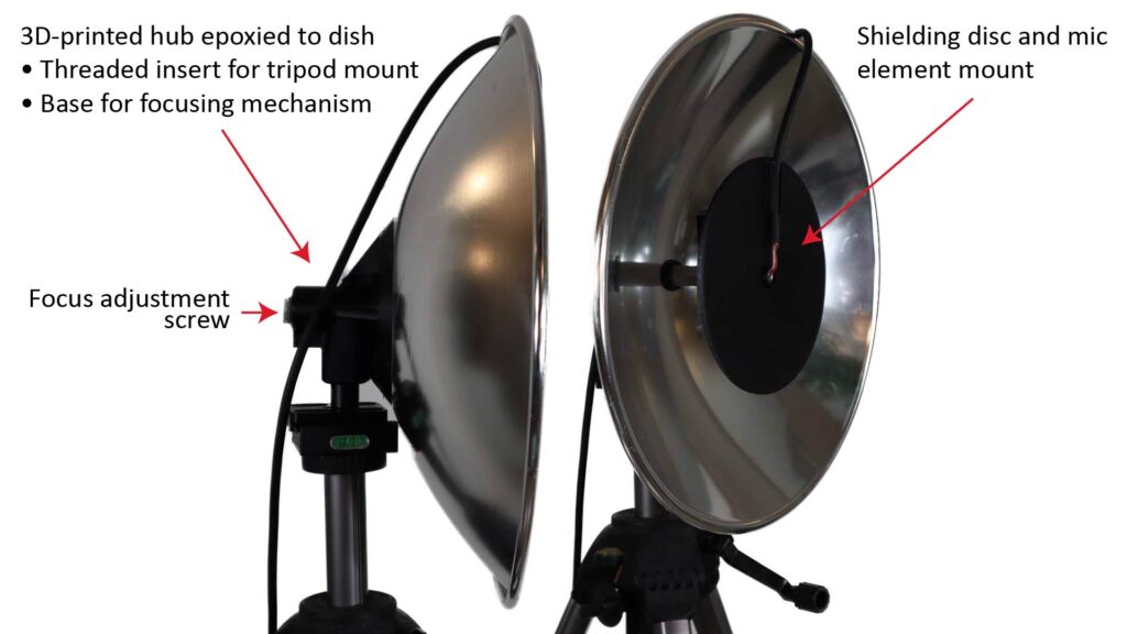
This particular DIY microphone includes a 3D-printed hub with threaded focusing mechanism to adjust the microphone element position. However, I’ve found that these dishes are so accurately made that the specified focal length is spot-on, so a threaded focusing mechanism isn’t really necessary.
If you’re curious about the purpose of the shielding disc in front of the microphone element, keep reading…I’ll address in detail later in this post.
Using a beauty dish
The ambiguously-named beauty dish is a dish-shaped accessory reflector for photography flash lights. Both rigid and collapsible beauty dishes are available, with only the rigid ones having a true parabolic shape. These rigid parabolic dishes are available in diameters of 12, 16, and 21 inches at prices of about $40 to 120 dollars.
Here’s a DIY parabolic microphone made from a 12-inch beauty dish reflector:
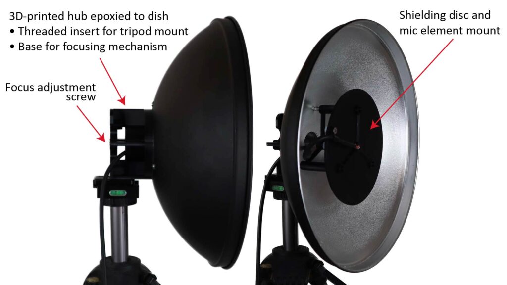
One advantage of these dishes is that they often come with a diffuser sock that can be attached to the dish when more diffuse light is wanted. I’ve found that some of these diffuser socks are reasonably transparent acoustically and can help attenuate wind noise in outdoor applications.
Using a dish intended for use in a parabolic microphone
By far the easiest option, but by far the most expensive, is to buy a dish that was originally intended for use in a parabolic microphone. However, if you go this route, it’s essential to buy only from a reputable source—and to pay attention to the product reviews before buying. Highly-regarded sources are Klover, Telinga, and Wildtronics LLC.
Microphone element considerations for parabolic microphones
While the diameter of the dish is the dominant factor in the performance of a parabolic microphone, the choice of the microphone element also has a significant impact.
Microphone Effective Input Noise (EIN), aka self-noise
The microphone EIN, which I discuss in the EIN section of my post on the 4 key microphone specifications, is a measure of the noise generated by the microphone itself.
In a parabolic microphone used in relatively noisy conditions, the total noise at the output will typically be dominated by off-axis ambient noise, making a low EIN relatively unimportant. In contrast, in a studio microphone used in an extremely quiet room, the microphone self-noise can contribute significantly to the total noise, making a low EIN very important. This figure from my post on long-range microphones shows the total noise as a function of ambient noise for various levels of microphone self-noise.
So a low microphone element EIN isn’t as important in a parabolic microphone as it is in a studio microphone. However, it can make a significant difference in performance in quieter environments and applications for which sound quality is important, such as videography.
The following figure shows the projected range of two parabolic microphones, one with an 8-inch dish and one with a 26-inch dish, for 50 percent speech intelligibility and for three levels of microphone EIN, in the “General” usage scenario previously described:
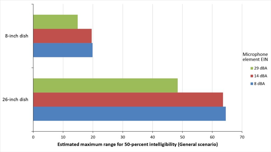
Note that reducing the EIN from 29 dBA (typical of a mediocre ECM element) to 14 dBA (typical of a high-quality ECM element) significantly increases the projected range, but further reducing the EIN to 8 dBA (typical of an extremely high-quality element or element array) makes relatively little difference in this particular scenario.
The assumed ambient noise profile in the General scenario assumed in Figure 15 has a broadband SPL of 35 dBA, which is typical of a fairly quiet indoor setting; if the ambient noise were even lower (such as in a professional recording studio), then the 8 dBA EIN would yield a greater benefit.
So, while a relatively high EIN of 30 dBA might be acceptable in a relatively noisy environment when sound quality isn’t crucial, an EIN of 15 dBA or less is definitely beneficial to keep the microphone self-noise below the ambient noise in more typical environments. And since even inexpensive electret condenser elements are capable of providing such an EIN, there is no reason to use a noisier element.
Microphone polar pattern
Ideally, the microphone element in a parabolic microphone should have a polar pattern that is just wide enough to “see” the entire dish, and no wider:
- If the pattern isn’t wide enough to see the entire dish, then some of the dish area is wasted, reducing the gain and directivity provided by the dish..
- On the other hand, a pattern that’s too wide will admit more off-axis noise, also reducing directivity.
In my experience, it’s better to have a pattern that’s too wide than one that’s too narrow.
If you’re using a dish with a high f/D ratio (such as a repurposed satellite dish), then it might seem that a cardioid pattern would be close to optimum. In fact, some online sources recommend the use of a cardioid microphone regardless of the f/D ratio. However, there are two issues with this:
- Small microphone elements with cardioid patterns are harder to find and more expensive than those with isotropic patterns, and generally have a higher EIN.
- A cardioid pattern provides limited benefit at high frequencies when the dish provides high gain and directivity. And the benefit is also limited at low frequencies where the dish provides no gain, because the cardioid’s null is pointed toward the sound source.
On the other hand, if you’re using a dish with a low f/D ratio, you definitely need an isotropic pattern to take full advantage of the dish’s capture area.
However, an isotropic pattern does have one disadvantage. At mid-range frequencies where the dish provides only a modest amount of gain, phase differences between the direct sound from the source and the reflected sound from the dish can cause comb-filter-like effects in the frequency response. However, these effects can be minimized, as discussed below.
Diaphragm size
Microphone elements with large diaphragms are prized for many audio applications. However, they have issues when used with parabolic microphones:
- Because the dish concentrates the sound in a relatively small area at the focal point, the large area of the diaphragm is wasted (especially at higher frequencies). Another way of looking at this issue is to consider the well-known fact that a large-diameter microphone becomes “beamy” at wavelengths comparable to or smaller than the width of the diaphragm, so that it can’t “see” the whole inside of the dish (and therefore doesn’t benefit from the full dish gain).
- Microphones with larger diaphragms are relatively expensive and harder to mount.
On the other hand, an element with a very small diaphragm will theoretically be more sensitive to errors in the microphone position or inaccuracies in the parabolic shape of the dish, although I haven’t found this to be a problem in practice.
So there is an optimum diaphragm size for every parabolic microphone, but there is no way to determine that optimum size without a lot of testing. In my experience, a diaphragm diameter of about 10 mm seems to work well, but I can’t say that it’s optimum.
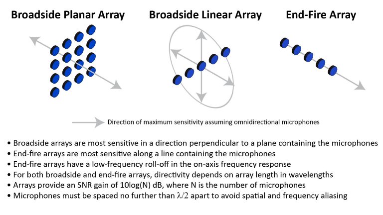
Use of microphone element arrays with parabolic microphones
As I explain in how array microphones work, an additive array of N microphone elements provides an SNR gain of 10log(N). The array output will have an EIN that is lower than the EIN of the individual microphone elements by the amount of this gain.
So, an array of 4 elements with an EIN of 14 dBA will have an effective EIN of 14 – 10log(4), or just 8 dBA. This is an extremely cost-effective way to achieve a low EIN with relatively inexpensive microphone elements. In fact, virtually all of my DIY studio microphones use small arrays for this very reason.
At least one manufacturer, Wildtronics LLC, apparently uses an array configuration with their parabolic microphones to minimize the microphone EIN: the online specs for their “Pro” parabolic microphones (see for example https://www.wildtronics.com/parabolic.html#.YyFGS7TMJ9M) refer to a microphone array with a noise floor of 10 dBA, which is quite impressive.
However, as with a single element with a large diaphragm, an array of microphone elements will become “beamy” at wavelengths comparable to or smaller than the width of the array, and therefore can’t benefit from the full dish gain.
Further, obtaining the full array gain of 10log(N) requires that the signals from all of the microphone element be perfectly in-phase, and this isn’t the case at higher frequencies due to the physical displacement of the elements.
So, when used with a dish, the primary EIN benefit of an array will be at lower frequencies. This benefit could be significant under some circumstances (otherwise Wildtronics wouldn’t be doing it), but I haven’t yet seen the need for it.
Recommended microphone element for parabolic microphones
Based on the considerations outlined above, I prefer to use a single high-quality Electret Condenser Microphone (ECM) element in my parabolic microphones. My microphone element of choice is the AOM-5024L-HD-R by PUI Audio, Inc. (see the spec sheet at PUI’s website), which offers the following specs:
- An SNR of 80 dB, which corresponds to an EIN of just 14 dBA.
- A diaphragm diameter of about 10 mm.
- A -3dB frequency response of 20 Hz to 20 kHz.
- A unit cost of about $3 from a variety of suppliers (including Digi-Key and Mouser).
As previously shown in Figure 15, an EIN of 14 dBA is low enough to be a non-issue in the General scenario (and should be low enough for all but the lowest-noise environments), and the diaphragm diameter is close to ideal
In fact, the AOM-5024L-HD-R is an excellent element for just about any DIY microphone application. By the way, if you’re interested in learning more about microphone specifications, check out The 4 key microphone specifications and why they’re important.
Using an isotropic microphone with a parabolic reflector
Microphone elements with isotropic patterns are the least expensive, most readily available, and (in some ways) the highest-performing type of microphone element. However, as previously discussed, they present two issues when used with parabolic reflectors:
- An isotropic pattern will pick-up off-axis ambient noise.
- An isotropic pattern will also pick-up on-axis sounds directly, in addition to the reflected on-axis sound collected by the dish.
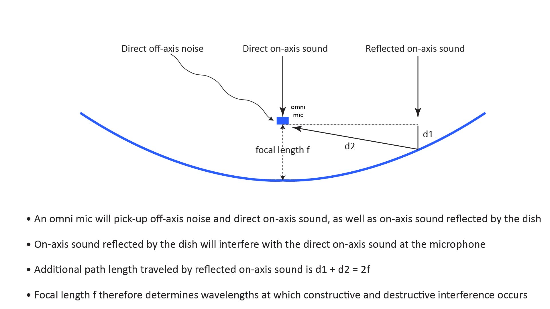
The reflected on-axis sound reaching the microphone from the dish travels a longer distance than the on-axis sound that reaches the microphone directly. This additional distance is equal to twice the focal length, and causes a phase delay that results in a comb-filter-like ripple in the microphone’s frequency response.
Both the off-axis noise and interference effects are mitigated by the fact that only the reflected on-axis sound from the dish experiences the dish gain. So, because the dish gain increases with frequency, these effects also become less significant with increasing frequency.
Probably the most significant audible issue when using an isotropic microphone is the interference-induced dip in the frequency response that occurs at the frequency at which the wavelength is 4 times the focal length (and harmonics thereof), because this dip will exacerbate the natural low-frequency roll-off in the dish’s gain. However, there is also constructive interference at the frequency at which the wavelength is twice the focal length (and harmonics thereof). Personally, I haven’t found the resulting comb-filtering effects to be objectionable, but they are noticeable.
Fortunately, both the off-axis noise and interference issues with isotropic microphones can be partially mitigated, at least to some extent.
Using a shielding disc with an isotropic microphone
The issues described above are due to the fact that an isotropic microphone’s pattern covers more than just the dish area. Unfortunately, we can’t physically block all of the undesired sound from reaching the microphone, because that would also block the desired sounds from reaching the dish.
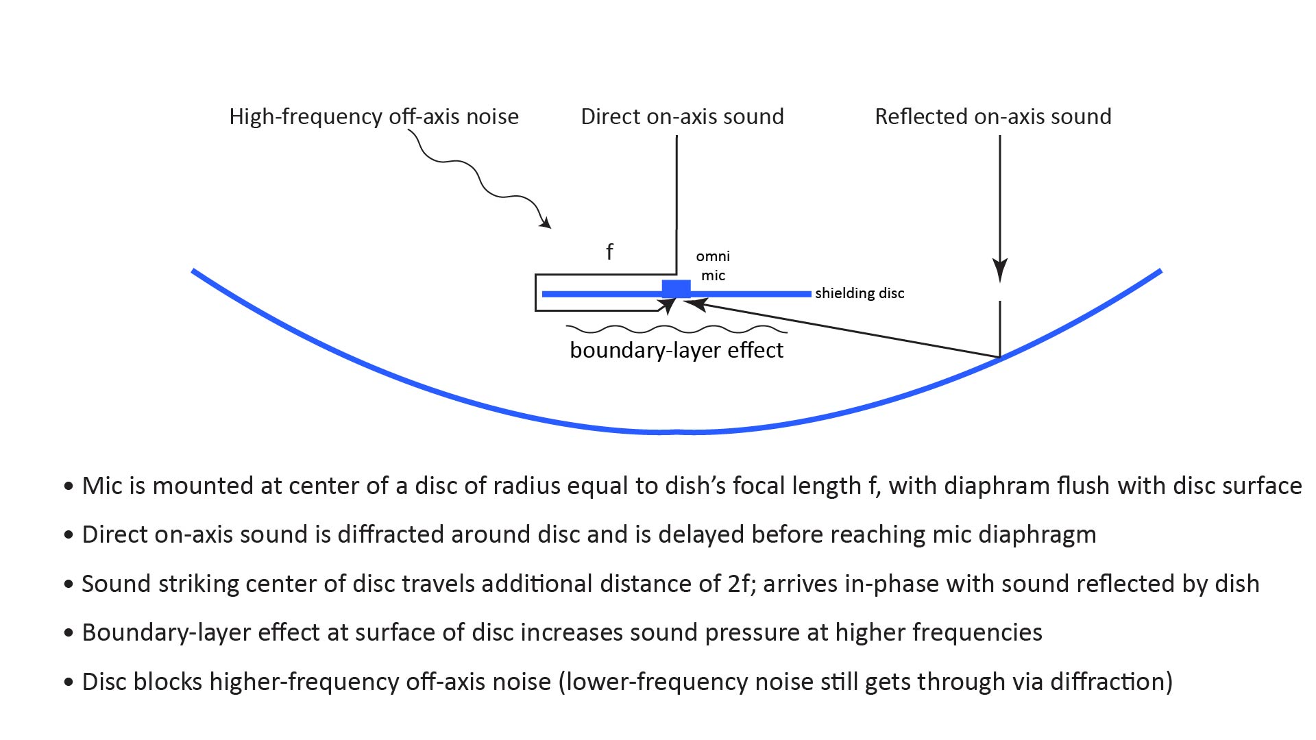
However, we can try to block at least some of the direct on-axis sound from reaching the microphone, by shielding it behind a disc whose diameter is smaller than that of the dish. This will also block some of the on-axis sound from reaching the dish, but the resulting loss in dish gain will be modest if the disc’s diameter isn’t too large.
Such a disc will have three benefits:
- It will amplify the sound reflected from the dish to the microphone via the boundary-layer effect.
- It will block higher-frequency on-axis sounds from reaching the microphone directly.
- Lower-frequency on-axis sound will still reach the microphone via diffraction from the disc’s edges, but the diffracted sound will be delayed, which can help to mitigate the interference effects described above.
Sound amplification via the boundary-layer effect
The boundary layer effect is a phenomenon in which fluid molecules near a surface tend to cling to that surface. When sound strikes a surface area whose dimensions are comparable to the wavelength of that sound, the boundary layer effect causes the surface to retard the movement of the air molecules, increasing the pressure. Isotropic microphones sense sound pressure, so if an isotropic microphone’s diaphragm is located very close to that surface, the SPL is receives will increase by 6 dB — but only for sounds whose wavelengths are shorter than the surface dimensions.
This boundary layer effect can be exploited in a parabolic microphone. One way to do this, disclosed in U.S. patent 6,408,080, is to mount a boundary-zone reflector at the focal point of the dish, and then position the microphone facing forward within the boundary zone of the reflector. The patent disclosure specifies that it is desirable that the boundary-zone reflector be concave, but does not discuss why. Presumably it’s to focus the reflected sound directly on the microphone.
However, the boundary layer effect can also be exploited by mounting the microphone on a flat disc, as shown in the previous illustration.
As previously stated, the boundary-zone amplification effect becomes significant only at wavelengths that are shorter than the disc diameter. For example, if the disc diameter is 6 inches, there will be little to no amplification below about 2,300 Hz. So, the larger the disc, the lower the frequency at which the boundary-layer amplification begins—but also the greater the loss in dish gain due to the obscured dish area.
Blocking higher-frequency sounds from directly reaching the microphone
Another benefit of the disc shown above is that it will block shorter wavelengths from reaching the microphone directly. As with the boundary-layer effect, only wavelengths which are shorter than the dimensions of the disc will be blocked; longer wavelengths will just diffract around the disc’s edges and eventually still reach the microphone’s diaphragm.
This mitigates two of the issues described above, but only at higher frequencies:
- It reduces some of the off-axis noise that would be otherwise picked-up by an isotropic microphone.
- It reduces some of the on-axis sound that would directly reach the microphone, interfering with the sound collected by the dish.
Mitigating interference between the direct and reflected on-axis sound
As noted above, wavelengths longer than the disc diameter won’t be blocked by the disc, and will still reach the microphone diaphragm via diffraction around the edges of the disc. However, the diffracted sound will delayed because it has to travel a longer distance around the disc.
Suppose the disc’s diameter is 2f (twice the dish’s focal length), as previously shown in Figure 17. Then the delay experienced by on-axis sound striking the center of the disc will exactly match the 2f delay experienced by the sound reflected from the dish’s surface. This will cause the direct sound striking the center of the disc and the sound reflected from the dish to arrive at the microphone in-phase, mitigating the interference effects.
Does this seem too good to be true? It is.
Unfortunately, sounds striking the disc anywhere but its center will experience a smaller delay, so they will still interfere with the sound reflected from the dish. For example, direct sound striking the periphery of the disc has to travel an additional path length of just f, instead of 2f, before reaching the microphone. And far more sound will strike the periphery of the disc than its center.
So with a disc diameter of 2f, there will still be destructive interference between the diffracted sound and the sound reflected from the dish. However, because the diffracted sound has to travel an extra distance of between f and 2f (depending on where it strikes the disc surface), the difference in the path length between the diffracted sound and the sound reflected from the dish is reduced: instead of a path length difference of 2f without the disc, the difference with the disc now ranges from just 0 to f. This doubles the frequency at which the comb-filter-like effects begin, while also reducing their amplitude. That’s a significant advantage because the dish gain increases by 6 dB per octave, further reducing the impact of the interference.
We could further suppress the interference by using a larger disc, but—as discussed below—the loss in dish gain rapidly becomes prohibitive as the size of the disc is increased.
Disadvantages of a shielding disc
Not surprisingly, there are also disadvantages with shielding an isotropic microphone behind a shielding disc.
Reduced dish gain
First, as previously noted, the disc will block some of the on-axis sound reaching the dish, reducing the dish gain. The loss in gain is equal to the ratio of the disc area to the dish’s mouth area. If we size the disc diameter as a multiple of the dish’s focal length, we can also express the gain loss as a function of the dish’s f/D ratio. The accompanying chart plots the gain loss versus f/D ratio for two disc diameters: 2f and 3f.
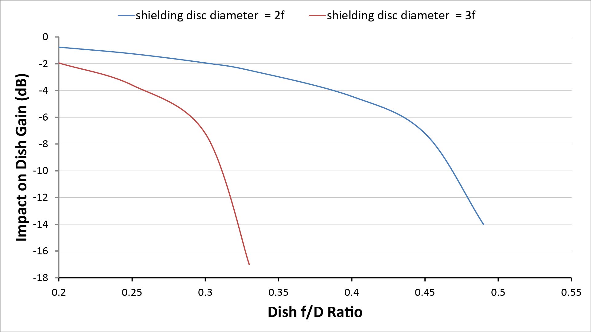
Notice that the plot for the 2f diameter disc stops short of an f/D ratio of 0.5, because a 2f diameter disc would cover the entire mouth of a dish with an f/D ratio of 0.5. Similarly, the plot for the 3f diameter disc stops short of an f/D ratio of 0.33, because at that point it would cover the entire dish’s mouth. Two conclusions can be drawn from this:
- The use of a shielding disc to mitigate inference effects is only practical for dishes with low f/D ratios.
- Even then, a disc of about 2f is the largest practical diameter that can be used.
Why don’t parabolic microphones use shielding discs?
Actually, they do.
The first time I personally became aware of the shielding disc concept was when, as a kid, I was reading a moldy yard-sale copy of the November 1960 issue of Science and Mechanics magazine. In it, there was an article entitled “Sound-Search Parabolic Mike” by Jack B. Thornton about building a parabolic microphone using a flying-saucer-style snow-sled for kids. The author stated, “Many mikes can be improved a bit in some locations by adding a 6- or 7-in disc of felt or fiberglass to the dead side to block unwanted sound.” And an accompanying figure shows a device exactly like the shielding disc of Figure 17.
Unfortunately, the author didn’t describe how the disc works, and it wasn’t until years later that I figured it out. Since then, I’ve built many parabolic microphones with such shielding discs, and more recently have been able to quantitatively measure their effects on performance (stay tuned to this blog for more on that subject).
As far as today’s commercial parabolic microphones are concerned, Wildtronics LLC (who appear to make the most advanced parabolic microphones available) seem to use a device very similar to the shielding disc described above. They refer to the device as a “patent-pending integral booster disc,” but unfortunately don’t provide any detail on how it works (https://www.wildtronics.com/parabolic.html#.YyFGS7TMJ9M).
Since the website refers to “patent pending” rather than “patented”, this isn’t yet an issue for someone who wants to build a DIY parabolic mic using a shielding disc for personal use. However, anyone considering manufacturing a parabolic microphone for public sale should bear in mind that some aspects of the shielding disc described above could eventually be covered by an issued patent.
Microphone mounting considerations for parabolic microphones
Achieving the full potential gain of a parabolic microphone requires mounting the microphone element so that the center of its diaphragm is located within a tenth of a wavelength or so of the dish’s focal point.
If you’re using a dish whose focal length isn’t precisely known and the parabolic microphone will be used to capture frequencies of more than a few kHz, the most effective way to do this is by adjusting the microphone element’s position while measuring its response to a test signal. We’ll call this process “aligning the microphone”.
The alignment process is greatly facilitated by a microphone mount that allows precise adjustment of the microphone’s position without obscuring the dish. Unfortunately, many DIY and commercially-available parabolic microphones use a simple clamp-type mount that requires a hand to be placed in front of the dish while adjusting the microphone position. It is possible to get reasonably close to perfect alignment with such a set-up, but it’s difficult and frustrating. On the other hand, building a more sophisticated microphone mount isn’t easy, either.
In fact, precise microphone alignment—and building a microphone mount that facilitates it—turns out to be the hardest part of building a well-performing parabolic microphone using a dish whose focal length isn’t already precisely known. And it’s even more difficult for parabolic microphones intended for capturing high-frequency sounds (like bird songs and insect noises), because even greater precision is needed.
Parabolic microphones versus other directional microphones
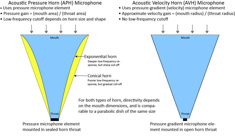
I have a detailed comparison of various types of high-directivity microphones in my anchor post on long-range microphones, but the bottom-line is parabolic microphones outperform other practical, comparably-sized directional microphones because of their gain and superior directivity. On the other hand, their 6 dB-per-octave low-frequency roll-off requires equalization, they’re harder to handle than shotgun microphones, and they’re harder to build than horn microphones.
Check out the following posts for more information on alternatives to parabolic microphones:
References
Of the many online references relevant to parabolic microphones, I find the following most useful:
- Ralph Martin and Jo Honold, “DIY stereo parabola,” blog post at https://avesrares.wordpress.com/2016/04/28/diy-parabola/, published April 2016. Accessed January 2021. Describes theory and construction of stereo parabolic microphones for birding applications.
- Chuck Peters, “How to Build a Parabolic Microphone Dish,” blog post at https://www.videomaker.com/article/f20/17144-how-to-build-a-parabolic-mic-dish. Accessed June 2021. Describes general principles of parabolic microphone operation and construction of a DIY unit based on a trash-can lid (but no equations or performance data).
- Wildtronics LLC website, https://www.wildtronics.com/. Accessed June 2021. Distributors of high-quality parabolic dishes and complete microphones. Includes articles on parabolic microphone theory and performance.
- Zhixin Chen, “Parabolic Dish Microphone System,” Ph.D thesis, Montana State University, available at https://www.montana.edu/rmaher/publications/maher_aac_0805.pdf [accessed June 2021].